This guide will be undergoing change as parts arrive for the new Flockbot design. This guide currently covers the Lower Plate construction of the Gripper and Wheel servo mounts, as well as the Upper Plate construction of the Raspberry Pi and the Raspberry Pi Camera.
|
The first step of the Flockbot construction is to unpack and inspect the Lower Plate. Lay out the plate as shown on the right.
| 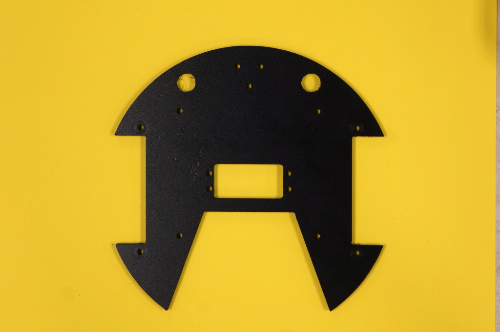
Larger/Higher Resolution Picture
|
Gripper Construction
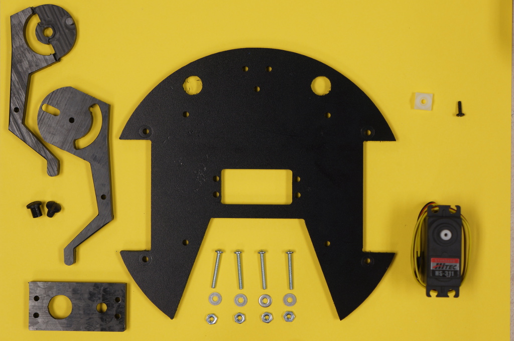
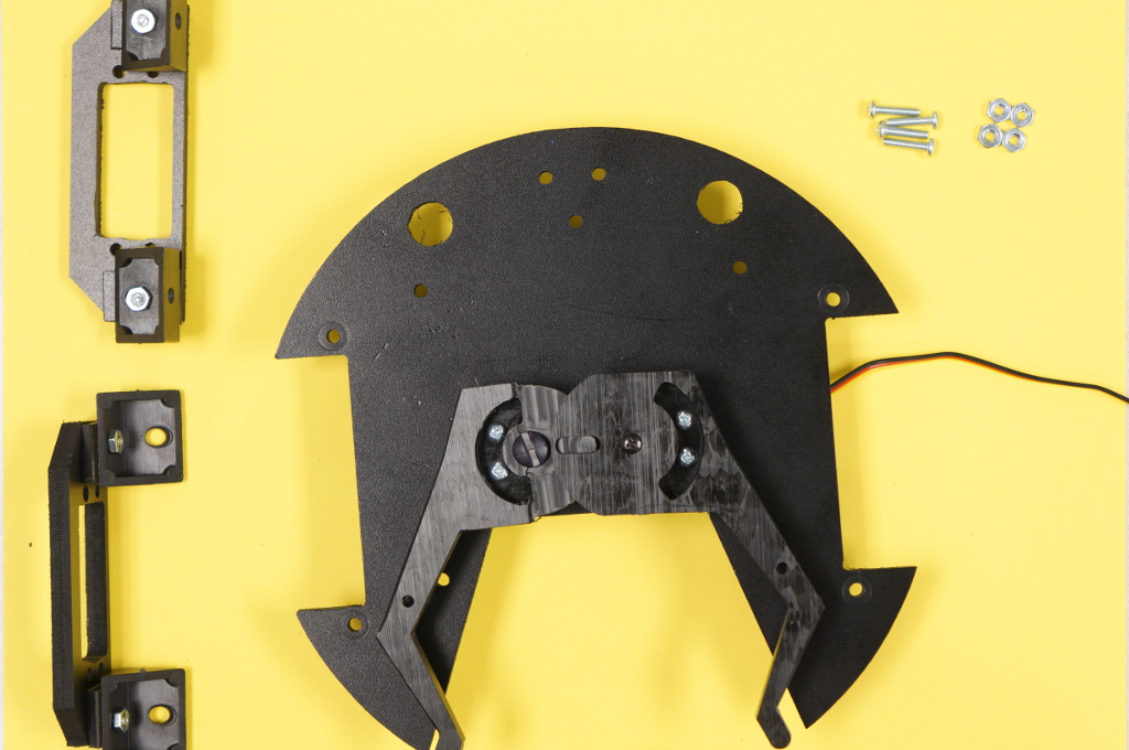
The first step of the Gripper construction is to lay out following items (shown in the image):
- Gripper Arms (Left and Right)
- Rectangular Servo Cover
- Plastic Screw and Nut
- HS-311 Gripper Servo (Remove the servo from the HS-311 Servo Box)
- Four #4-40 7/8" (Gripper) screws
- Four #4 Washers (Gripper)
- Four #4-40 Hex Nuts (Gripper)
- Servo Horn (Open the HS-311 Gripper Servo Box and remove the servo and the small, white rectangular servo horn.)
- Servo Screw (Remove the screw from the HS-311 Gripper Servo and remove the circular servo horn that is on that servo. Replace the circular horn back in the box.)
At this point, you should have the parts laid out as depicted in the image to the right.
| 
Larger/Higher Resolution Picture
|
|
The second step is to insert the servo into the Lower Plate.
- Place the servo in the central servo hole.
- Ensure the servo wire is facing to the right (and the Lower Plate is the same orientation as the image).
- Take the Plastic Nut portion in the smaller hole of the Rectangular Servo Cover
- Place the Rectangular Servo Cover over the Servo.
Your space should look like the image on the right.
| 
Larger/Higher Resolution Picture
|
|
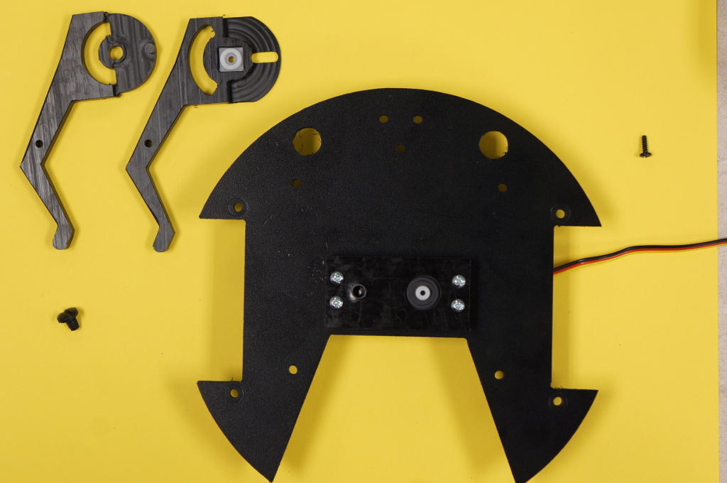
The third step is to screw the plate and servo down.
- Use the screws to screw the gripper plate through the servo and secure it into the lower plate.
- Ensure you use the washer and nut to secure the screw.
- Do not over-tighten the screws, but ensure the nuts are secure and will not rotate off.
- Take the small, white rectangular servo horn and place it inside of the gripper, as shown in the image.
Your space should look like the image on the right.
| 
Larger/Higher Resolution Picture
|
|
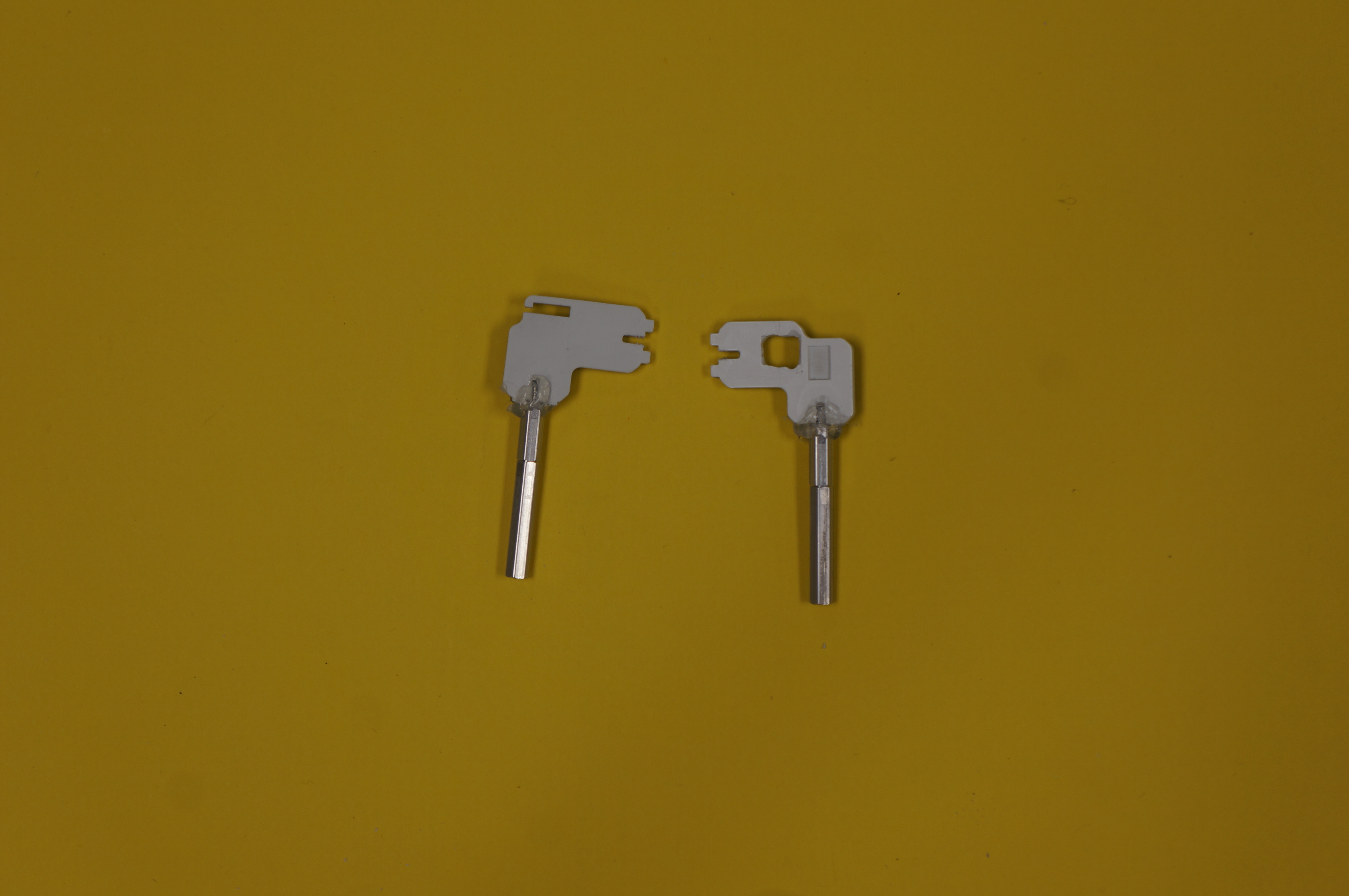
The final step is to attach the grippers.
- Attach the grippers as shown over the servo horn and plastic nut.
- The grippers inter-lock and will only fit when they are both symmetrically open.
- Use the plastic screw to screw over the plastic nut. This should be hand tight.
- Use the servo screw to screw over the servo horn. This should be hand tight.
Your space should look like the image on the right.
| 
Larger/Higher Resolution Picture
|
Wheel Servo Mount Construction
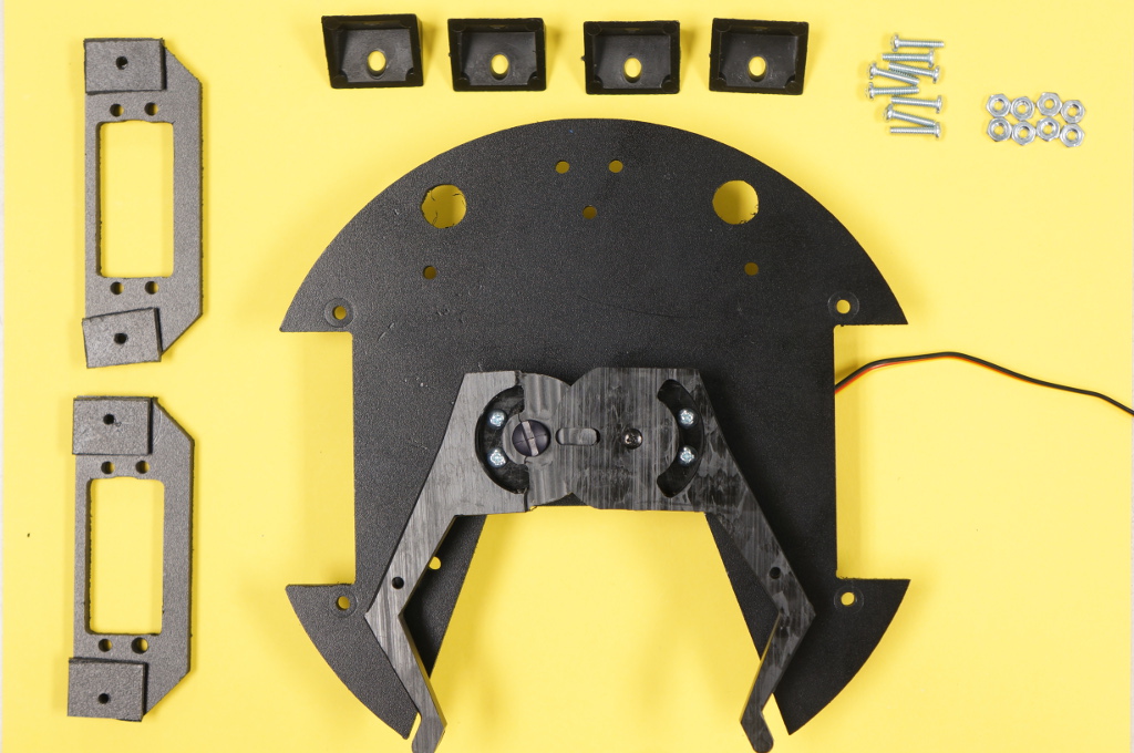
The first step of the Wheel Servo Mount construction is to lay out following items (shown on the image to the right):
- Two Flange Servo Brackets
- Four Angle Brackets
- Four Angle Bracket Risers
- Eight #4-40 1/2" (Wheel) Screws (rounded top screws)
- Eight #4-40 Hex Nut
At this point, you should have the parts laid out as depicted in the image to the right.
| 
Larger/Higher Resolution Picture
|
|
The first step is to lay the Angle Bracket Risers over the outermost holes on the Flange Servo Brackets. The purpose of these risers is to raise the angle bracket up by 1/8" in order to make room for the servo screw nuts. These are wide risers so the area under the angle bracket can be maximized to increase friction and hold the angle brackets on better.
| 
Larger/Higher Resolution Picture
|
|
The second step is to attach the Angle Brackets to the Flange Servo Brackets.
- Place the Angle Brackets over the Angle Bracket Risers.
- Keep in mind to align the Angle Bracket Risers to line up with the hole and to maximize the area under the angle brackets.
- Use four screws and four nuts to attach the four Angle Brackets.
The image on the right shows one of the Flange Servo Brackets on its side, to show two views of the attachment.
| 
Larger/Higher Resolution Picture
|
|
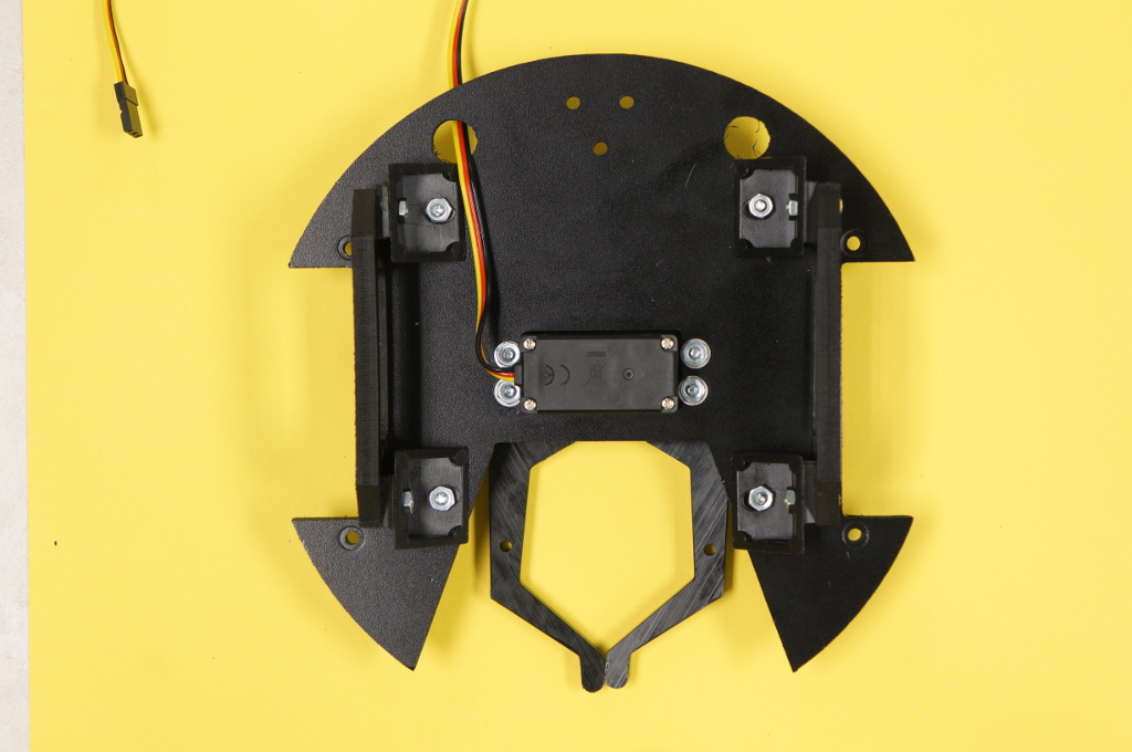
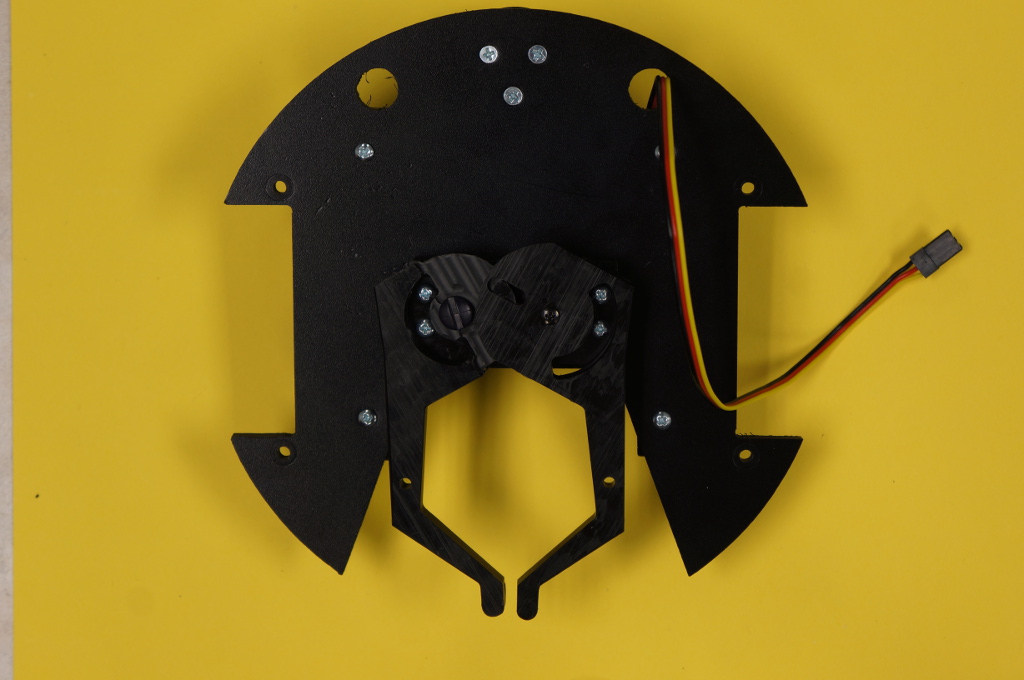
The third step is to attach the Angle Brackets to the Lower Plate.
- Flip the Lower Plate over on its back.
- Screw the Angle Brackets into the Lower Plate.
- The opening on the Flange Servo Bracket should be offset to the rear (rounded end) of the Lower Plate.
This view of the robot is from the bottom of the Lower Plate. Notice how the attached mounts look.
| 
Larger/Higher Resolution Picture
|
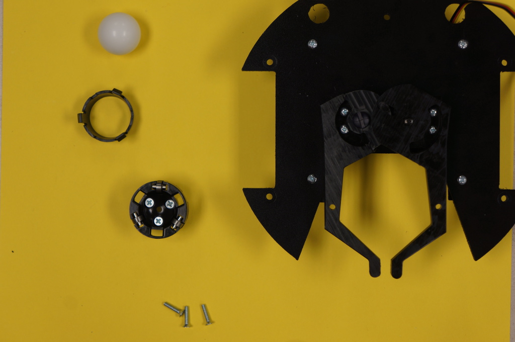
Ball Caster Construction
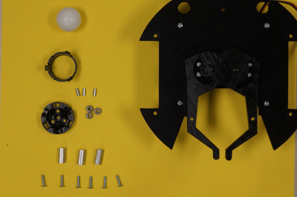
The first step of the Ball Casterconstruction is to lay out following items (shown on the image to the right):
- Ball Caster Kit
- Ball
- Upper Housing
- Lower Housing (with screw holes)
- Three Rings
- Three Pins
- Three #4-40 F-F RSR 5/8" Ball Caster Risers
- Six #4-40 1/2" Flat Ball Caster Wheel Screws
- Note: These have a flattened head, not a rounded one.
At this point, you should have the parts laid out as depicted in the image to the right.
| 
Larger/Higher Resolution Picture
|
|
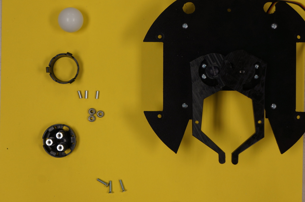
The first step:
- Take the Lower Housing and locate the three screw holes that form a triangular shape.
- Insert the three screws through these holes, from the inside to the outside.
- The flat head of the screw should be on the inner, circular side of the piece.
- Take the three #4-40 Risers and screw them into the screws.
- Tighten these by hand with a screwdriver.
The Lower Housing in the image here is upside down, with the three risers standing up.
| 
Larger/Higher Resolution Picture
|
|
The second step:
- Invert the Lower Housing (looking inside at the heads of the screws).
- Take each ring and place a pin through the center of it, then place that in the slot in the Lower Housing.
The Lower Housing in the image here is looking at the inside. Note the screw heads and the bearings (pin + ring).
| 
Larger/Higher Resolution Picture
|
|
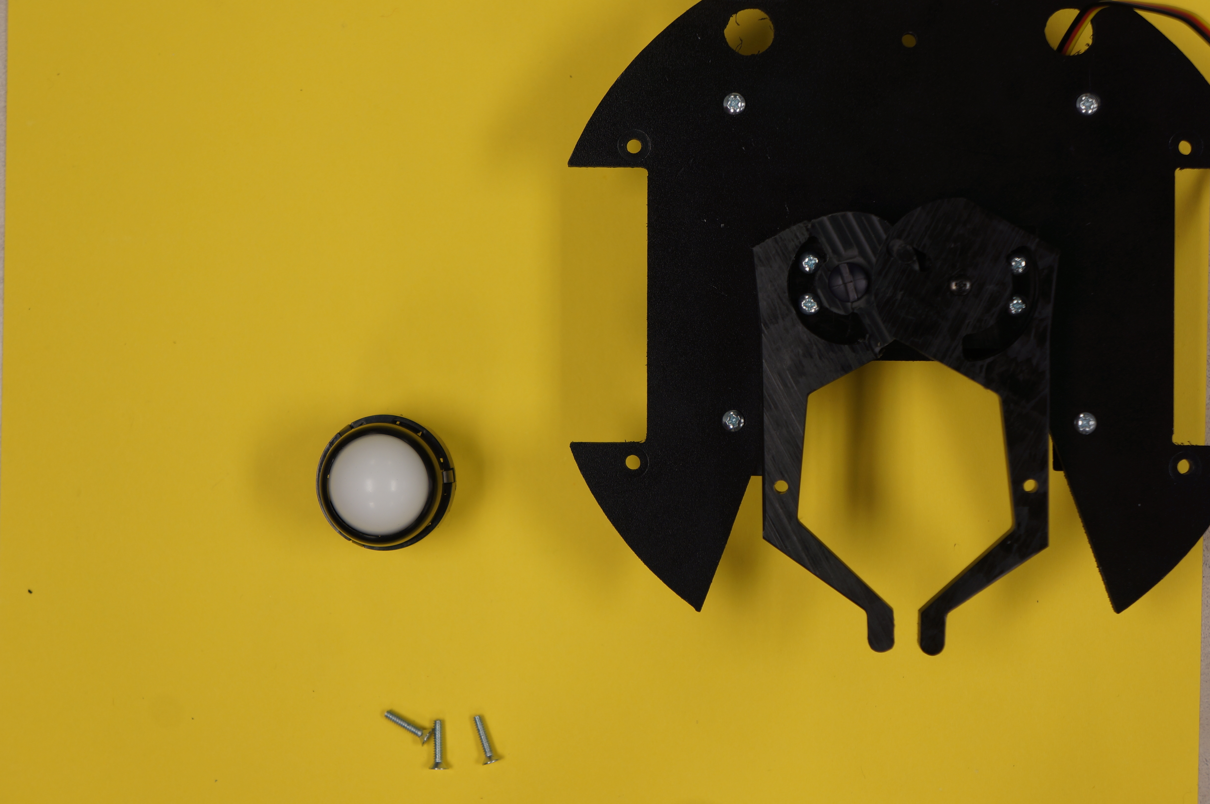
The third step:
- Place the ball into the Lower Housing, right over those screw heads.
- The ball will rest on the bearings.
- Take the Upper Housing and snap it own over the Lower Housing.
- This will encase the ball.
The completed Ball Caster and housing should look like the image.
| 
Larger/Higher Resolution Picture
|
|
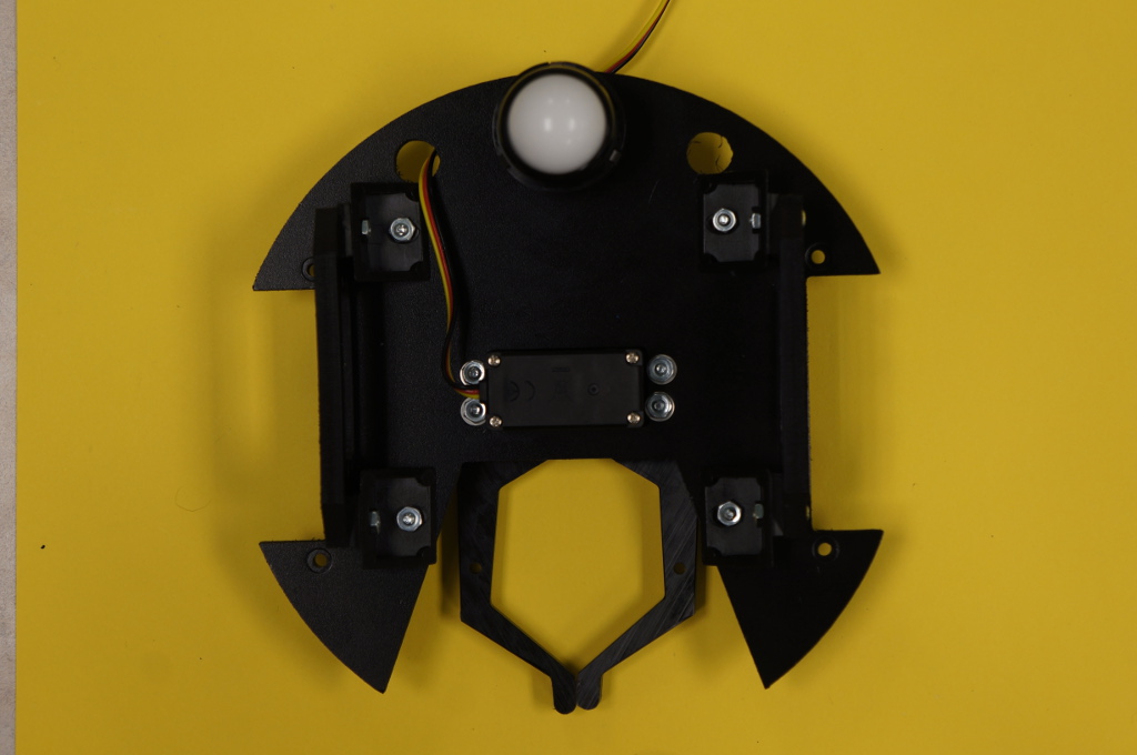
The final step:
- Screw the Ball Caster risers into the back of the Lower Plate
The completed assembly will look like the two images on the right. One from the top and one from the bottom.
| 
Larger/Higher Resolution Picture
|
|
| 
Larger/Higher Resolution Picture
|
Under Construction
Upper Plate
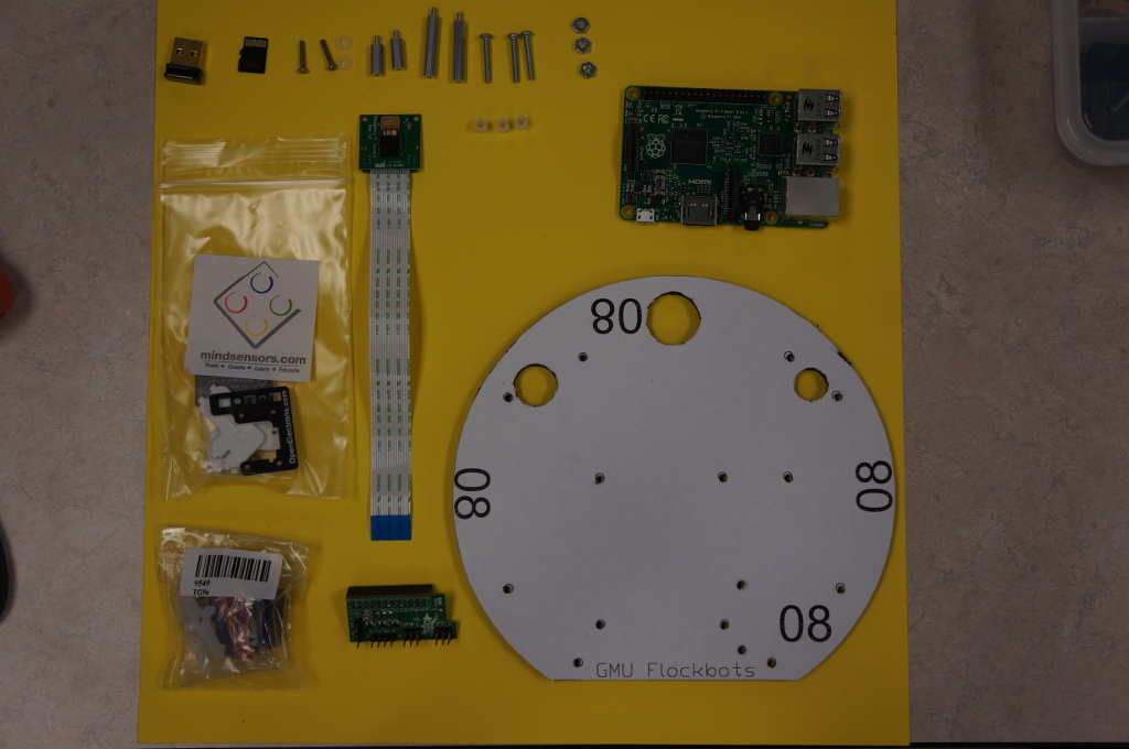
The following materials are used in constructing the Upper Plate (shown on the image to the right):
- 1 x Top Plate w/ Label
- 1 x Edimax Wi-Fi
- 1 x Flash Memory
- 2 x 2-28 x .25" screw
- 2 X 2-56 1/2" camera screws
- 2 x #2 washer camera
- 2 x 2-56 RSR 1/2" camera
- 2 x 2-56 RSR 1" camera
- 1 x mindsensors PiCam Mount Kit
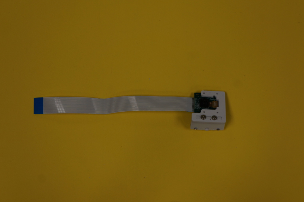
- 1 x camera board
- 1 x Micro-Servo
- 1 x BitWizard
- 3 x 4-40 3/4" RaspPi screws
- 3 x 4-40 hex nut RaspPi
- 3 x #4 1/4" spacer RaspPi
At this point, you should have the parts laid out as depicted in the image to the right.
| 
Larger/Higher Resolution Picture
|
Mounting the Raspberry Pi
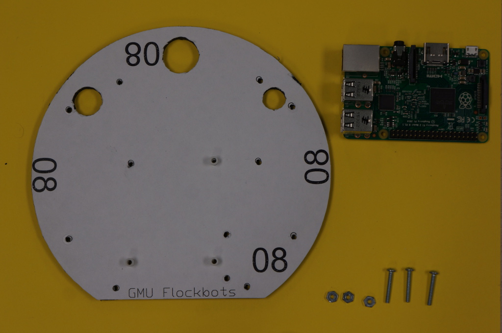
The first step:
- Set aside the Top Plate, the Raspberry Pi, the screws, the nuts, and the spacers to mount the Raspberry Pi
| 
Larger/Higher Resolution Picture
|
|
The second step:
- Place the spacers ontop of the three holes as seen in the image.
| 
Larger/Higher Resolution Picture
|
|
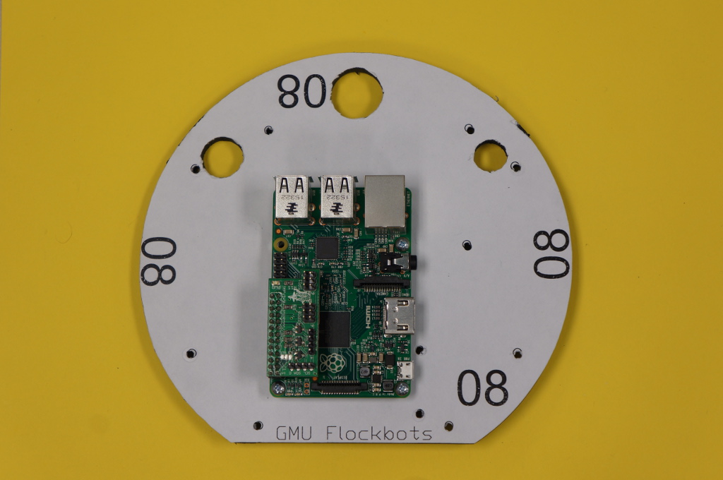
The third step:
- Mount the Raspberry Pi to the plate.
- Carefully set the Raspberry Pi on top of the spacers.
- Feed the screws through the mount points and secure the pi.
The successfully mounted Raspberry Pi will look like the image.
| 
Larger/Higher Resolution Picture
|
BitWizard
The first step:
- Attach the BitWizard to the pins on the far left of the RaspberryPi.
| 
Larger/Higher Resolution Picture
|
PiCam Mount
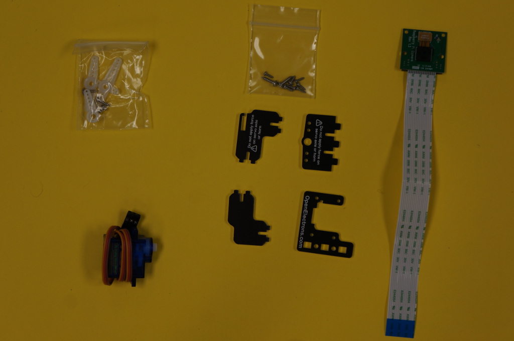
The first step:
- Set Aside all the materials necessary for constructing the PiCam Mount.
- Attach the 2-56 RSR 1/2" to the top of the 2-56 RSR 1".
- One of the pieces which holds the servo needs to have a bit cut out of it. Ask one of the members leading the build to show you how to cut it.
| 
Larger/Higher Resolution Picture
|
|
The second step:
- After the housing has been modified and the risers have been connected, attach the housing to the risers.
- Screw the risers into the bottoms of the servo mount. There are no threads in the housing but it works.
- Once the risers are connected to the mount pieces, dab some hot glue on it to make sure it doesn't wiggle around.
| 
Larger/Higher Resolution Picture
|
|
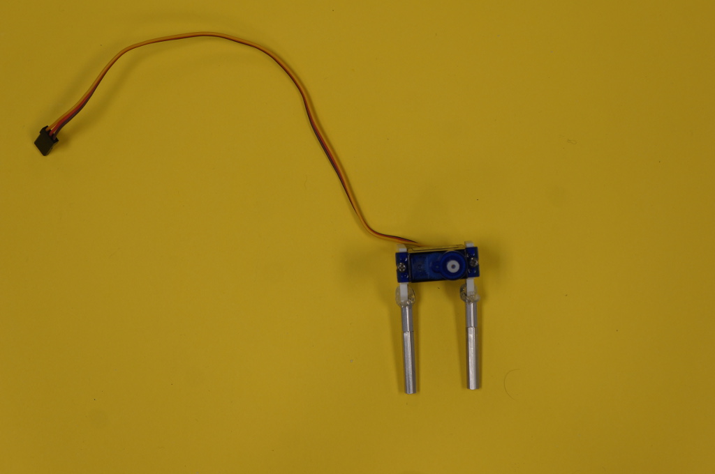
The third step:
- Connecting the servo.
- Place the Micro-Servo between the two constructed posts. The wire coming out of the servo should be on the side touching the post which had to be cut.
- take 2 screws from the bag in the kit and connect the Micro-Server to the posts.
- wrap some blue electrical tape around the Micro-Server to prevent it from wiggling.
| 
Larger/Higher Resolution Picture
|
|
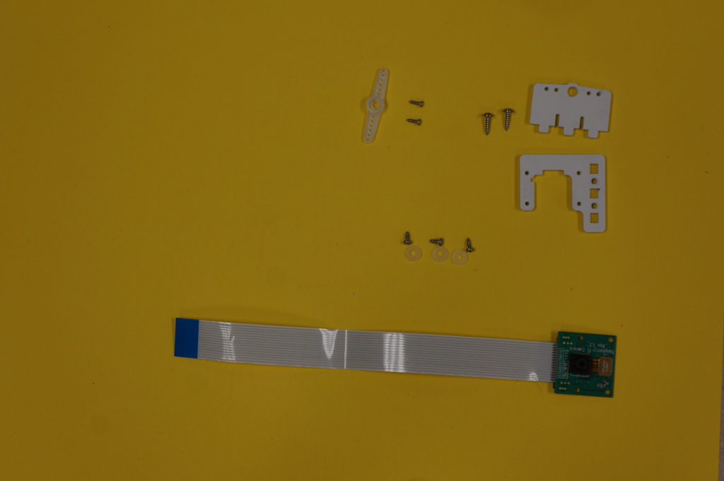
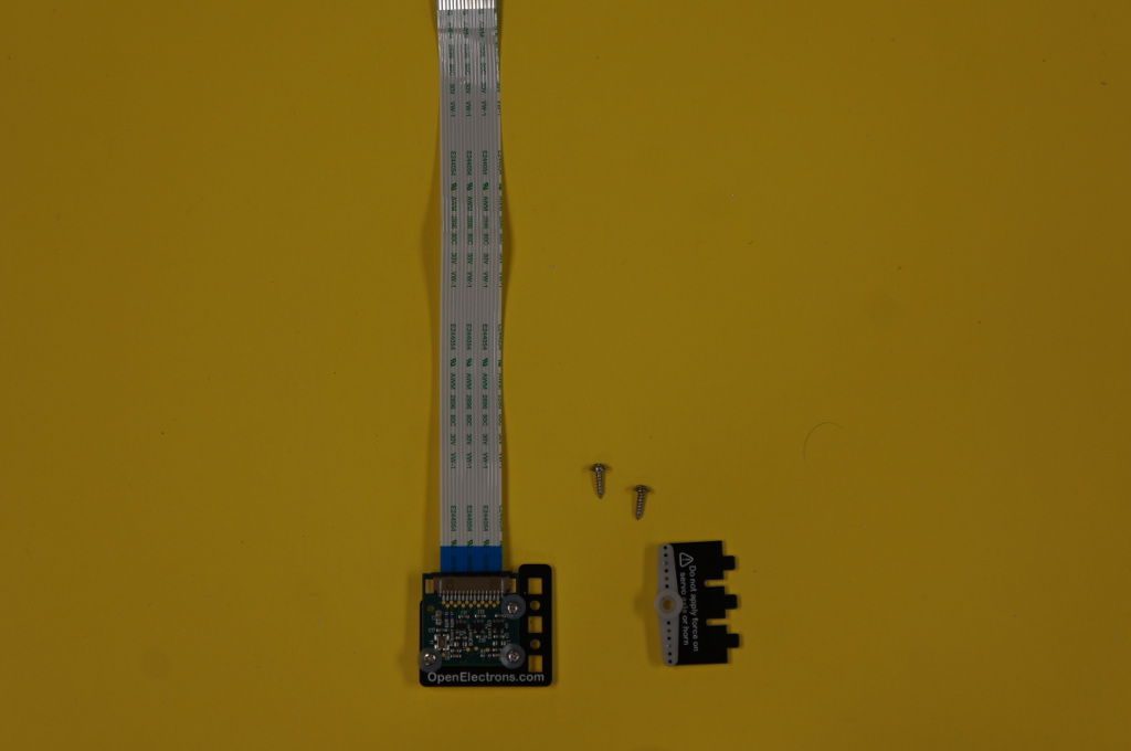
The fourth step:
- House the PiCam with the remaining pieces in the kit.
- The 2 2-28 x .25" are not included in the kit. They are found in the tackle box.
The first image is all the pieces for this step laid out.
The second image is what it will look like once pieces are secured to the mounts.
- Make sure to put the washers between the screws and the camera
The third image is the two mounts connected.
| 
Larger/Higher Resolution Picture
|
|
| 
Larger/Higher Resolution Picture
|
|
| 
Larger/Higher Resolution Picture
|
|
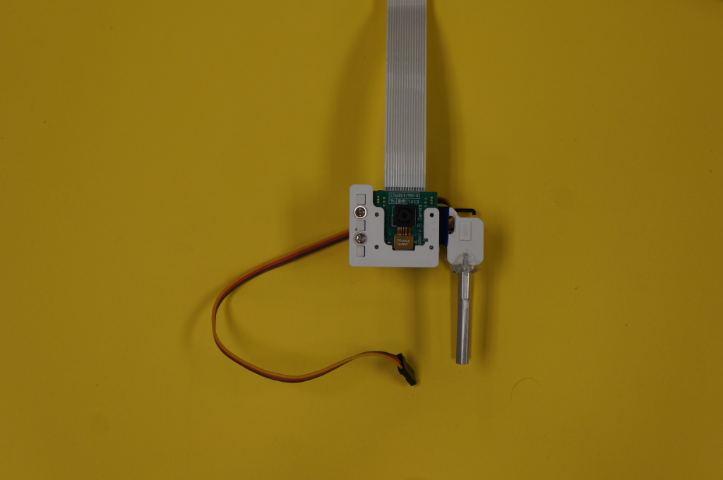
The fifth step:
- Attach the camera to the Micro-Servo via the servo horn
- The horn slides onto servo shaft. It shouldn't take much force.
| 
Larger/Higher Resolution Picture
|
|
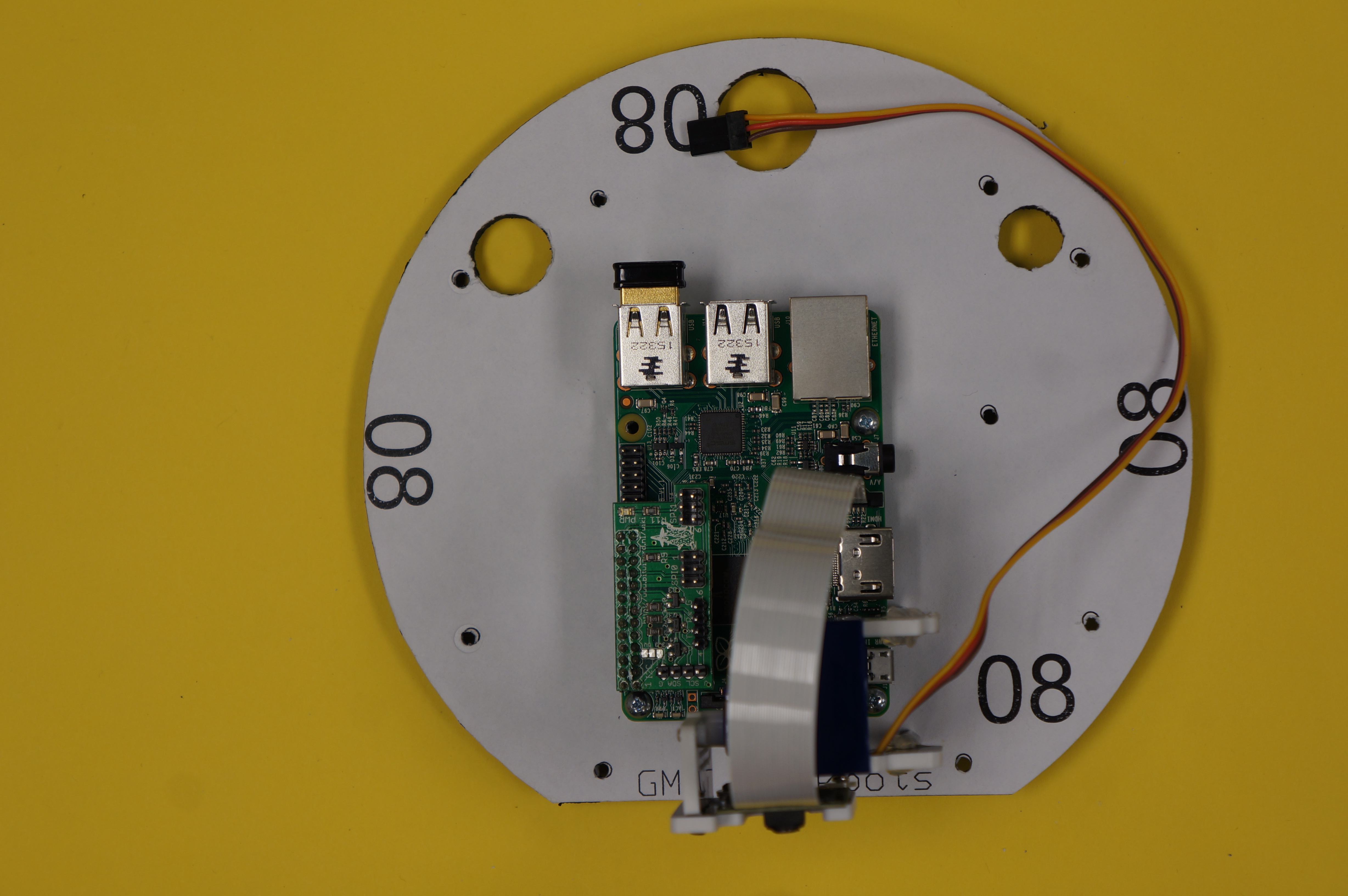
Final step:
- use the remaining screws and washers to connect the posts holding the camera to the plate.
- seat the ribbon cable coming out of the PiCam to its port on the Raspberry Pi
- really make sure this is seated correctly.
- once its seated push the clip down the PiCam should be connected.
- Put the Edimax Wi-fi dongle into one of the USB ports and the SD card into the SD card slot
| 
Larger/Higher Resolution Picture
|
|
Continued in Construction Two
|
