This page continues with the construction, building the power circuit.
|
The first step of the power circuit is to lay out following items (shown in the image):
- 2 red, 2 black, 1 other (orange) 7-inch wire
- 1 red, 1 black 4-inch wire
- 2 red, 2 black 2.5-inch wire
- 1 red, 2 black 2-inch wire
- 1 UBEC (Battery Elimination Circuit)
- 1 51K ohm resistor (Green, Brown, Black, Red, Brown)
- 1 39K ohm resistor (Orange, White, Black, Red, Brown)
- 5 crimps
- 1 4 hole crimp housing
- 1 2 hole crimp housing
- 1 1 hole crimp housing
- 2 Anderson Power Pole Pair (Red, Black)
- 4 Anderson Power Pole Crimps
- 1 Switch
At this point, you should have the parts laid out as depicted in the image to the right.
| 
Larger/Higher Resolution Picture
|
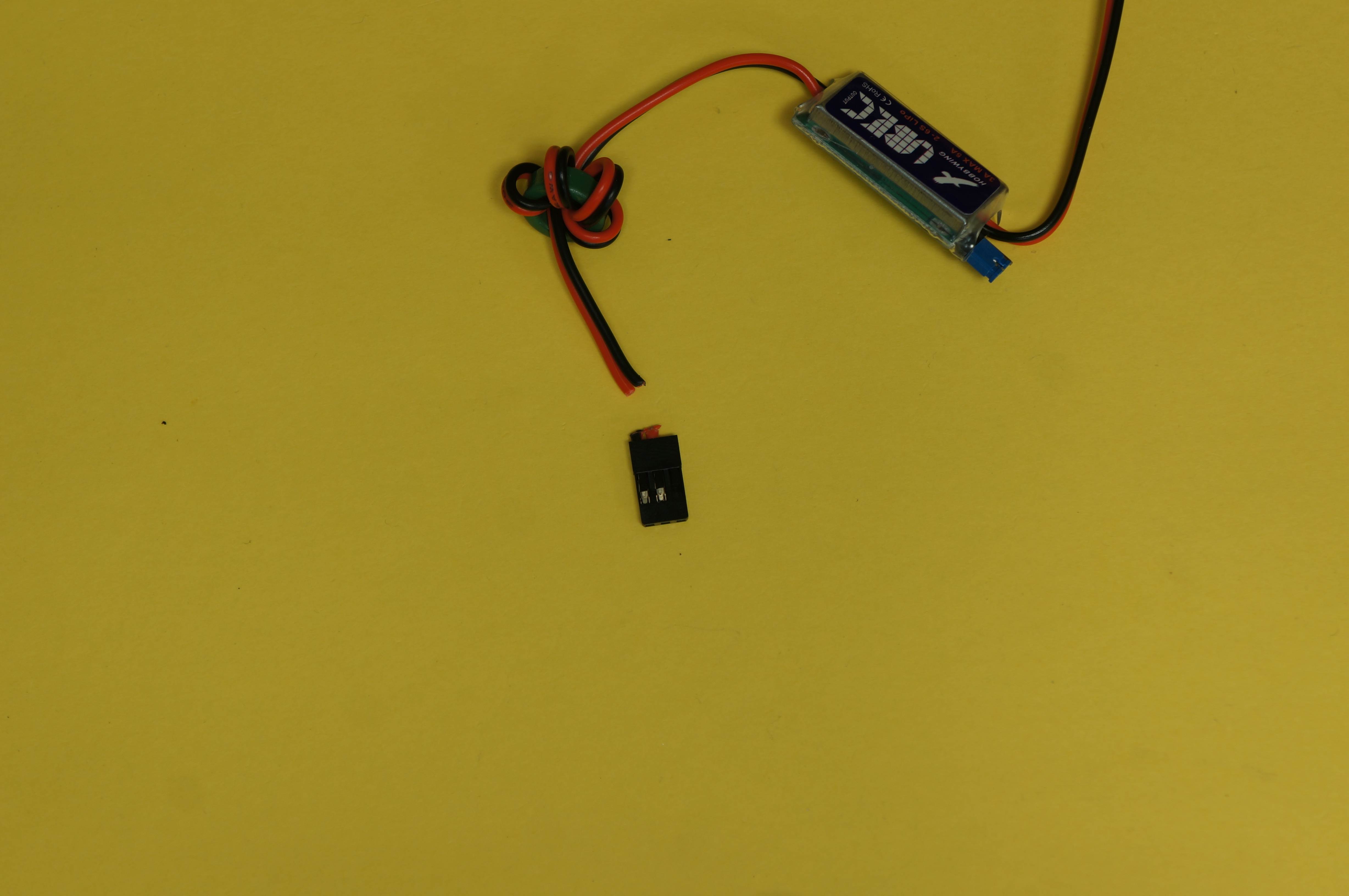
Ubec Preparation
The UBEC needs to have a small modification so that it can be used.
- Parts:
- Steps:
- Cut the Housing from the output line of the UBEC
- Make sure the power selector (Blue Jumper) is on 5v
| 
Larger/Higher Resolution Picture
|
The Power Switch
The first is to solder the power switch to its lead and shrink wrap them.
- Parts need:
- 1 black 2 inch wire
- 1 black 2.5 inch wire
- switch
- Steps:
- Solder the 2.5 inch black wire to the outside pin of the switch
- Solder the 2 inch black wire to the inside pin of the switch
- Shrink wrap the two pins
Your space should look like the image on the right.
| 
Larger/Higher Resolution Picture
|
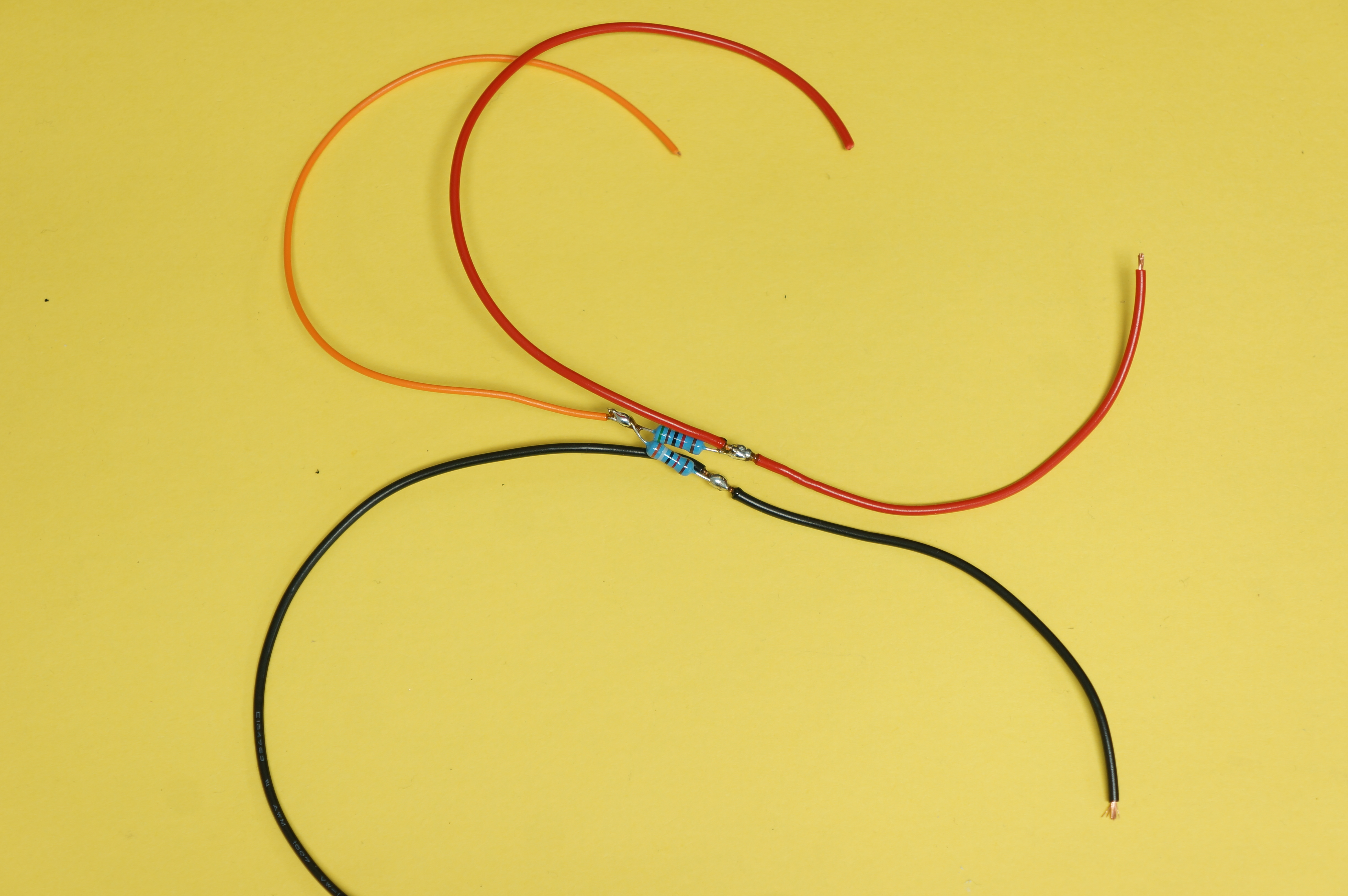
Inline Voltage Divider
- Parts:
- 1 red 4 inch wire
- 1 back 4 inch wire
- 1 red 7 inch wire
- 1 black 7 inch wire
- 1 other (orange) 7 inch wire
- 51K ohm resistor
- 39K ohm resistor
- Steps:
- First strip the ends on all the wires
- Next solder the two red wires in line
- Add a larger blob of solder for easier resistor mounting
- Tip: Push the wires together so that the strands are interwoven
- Repeat for the black wires
- Cut one end of each resistor short and twist the other ends together, cutting that short as well
- Tip: You can twist the resistor lead around the wires instead of cutting it
- Solder the short end of the 51K ohm resistor to the red wire, where the two wires meet with the twisted end facing in the direction of the twisted part of the resistors
- Do the same for the short end of the 31K ohm resistor but this time attach it to the black wires
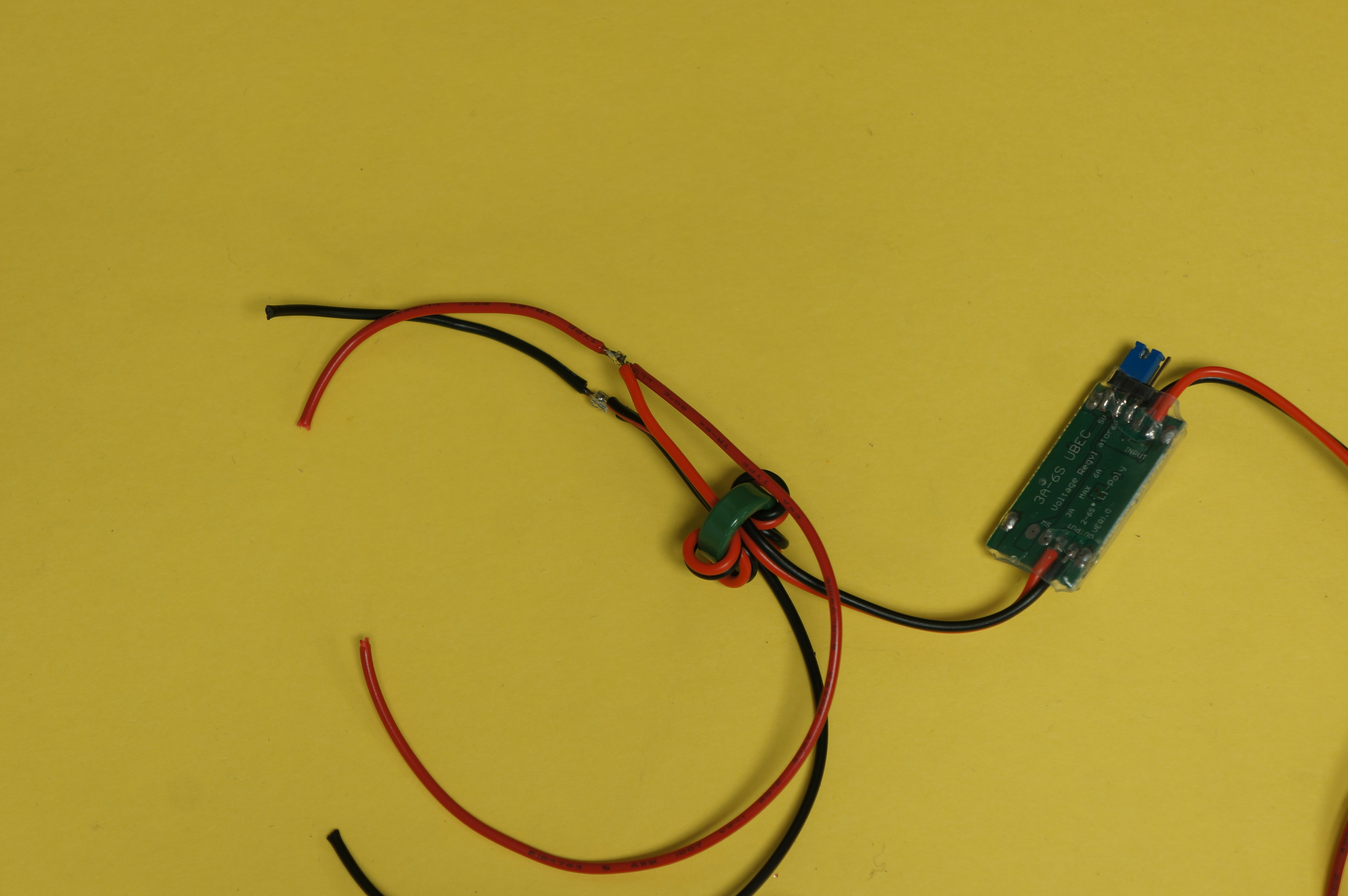
- Solder the twisted ends of the resistors
- Then solder the other color (orange) 7 inch wire to the twisted end
It should end up looking like the image on the right.
| 
Larger/Higher Resolution Picture
|
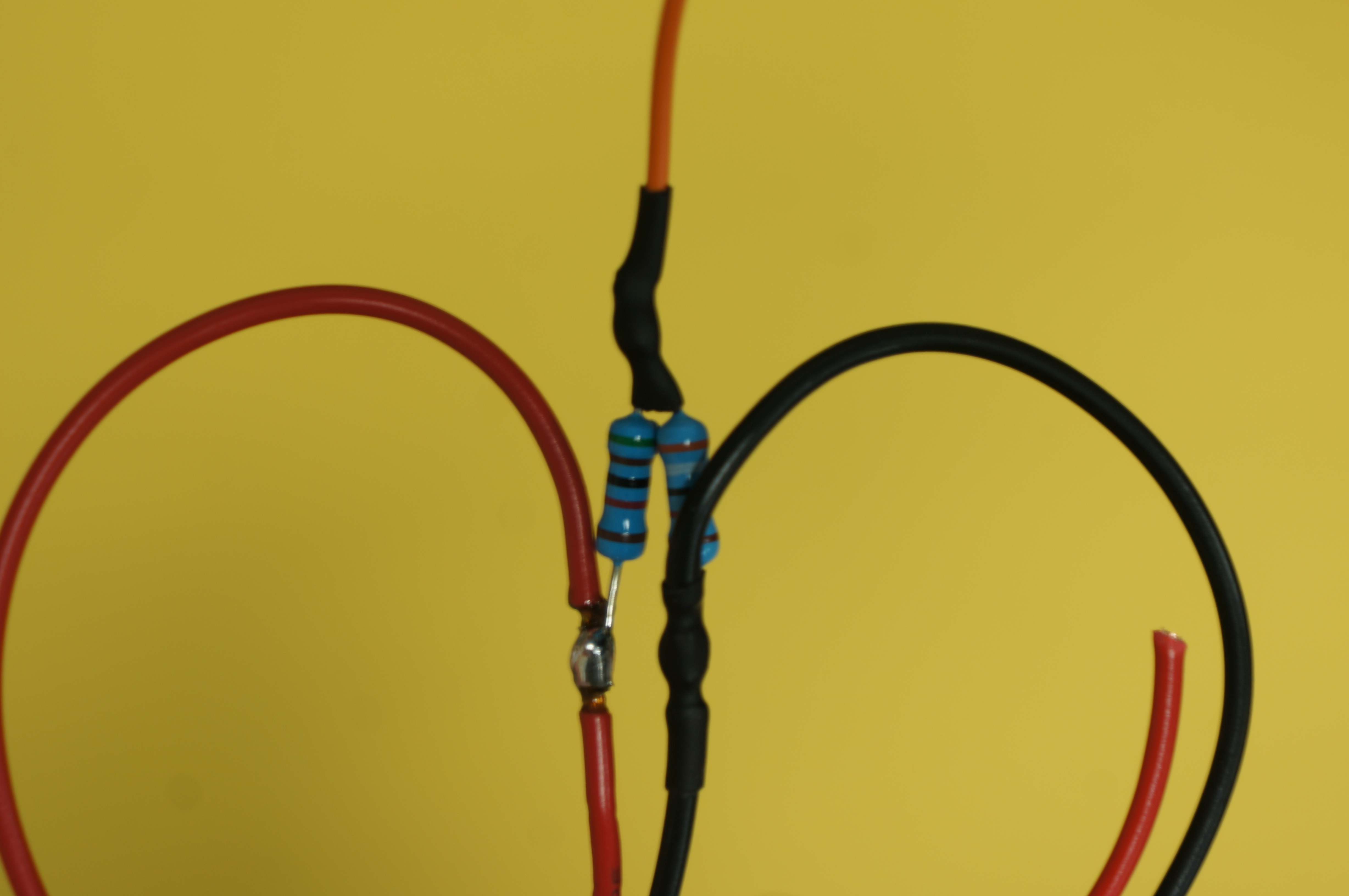
- Steps (Cont.):
- Next add shrink wrap the black and other colored (orange) wires where they have exposed solder joints
| 
Larger/Higher Resolution Picture
|
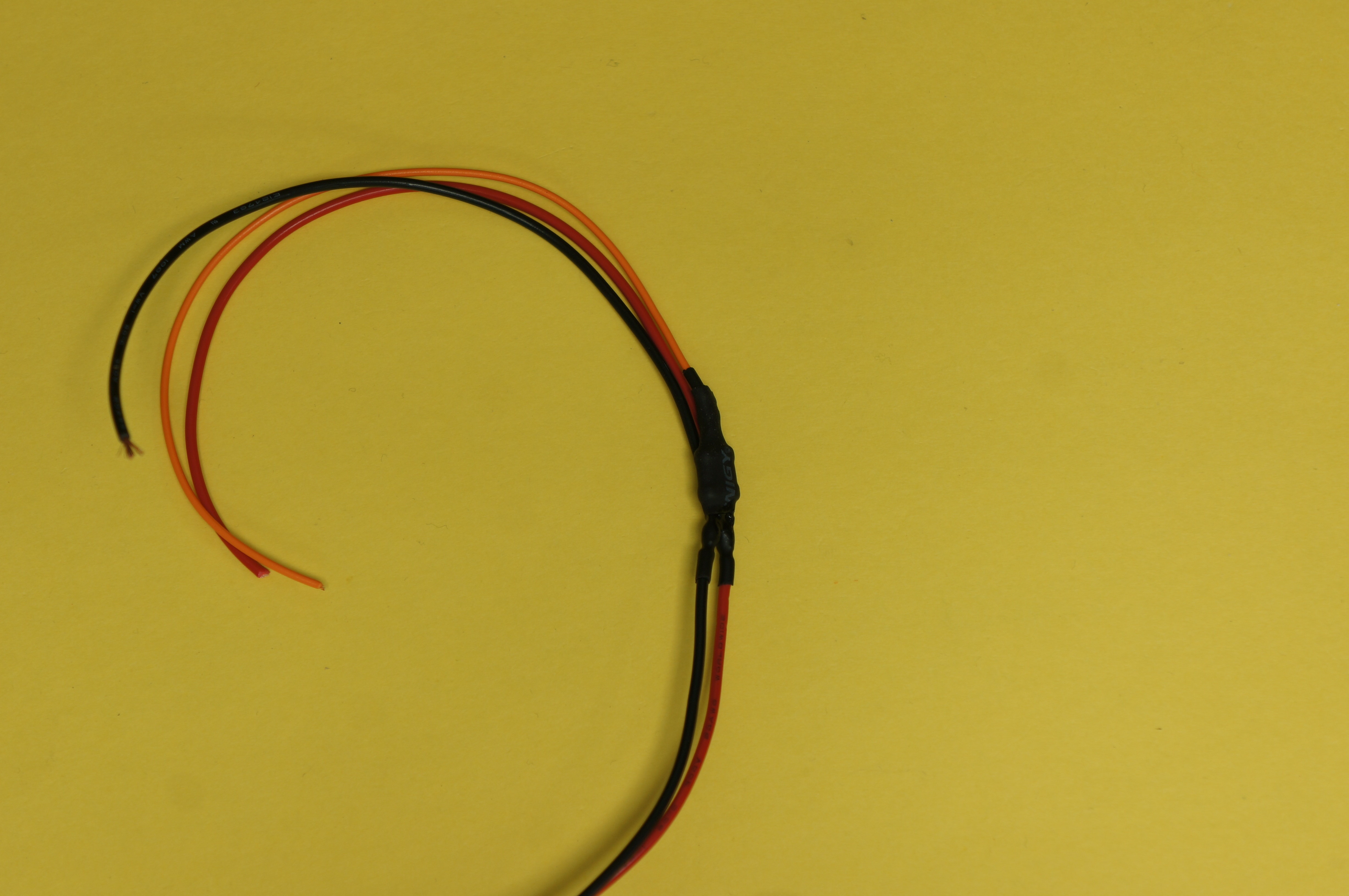
- Finish by adding shrink wrap over the resistors as well as any exposed section of the voltage divider
| 
Larger/Higher Resolution Picture
|
The First Y Split
- Parts:
- UBEC
- Completed Switch Section
- Completed Voltage Divider Section
- 1 red 2.5 inch wire
- Steps:
- First strip the ends on all the wires
- Next solder the two red wires in line
- Be sure to use the leads on the voltage divider that are not on the other color (orange) side
- With the UBEC on the side with the voltage divider
- Add a larger blob of solder for easier resistor mounting
- Tip: Push the wires together so that the strands are interwoven
- Tip: Put a piece of shrink wrap on the Switch longer lead (2.5 inch) so that you can use it later
- Repeat for the black wires, using the longer (2.5 inch) of the switch sections leads
- Next take the red lead from the UBEC and solder it to the joined red wires
- Repeat for the red lead of the UBEC and the red wires
- Add shrink wrap to all the solder joints
It should end up looking like the image on the right.
| 
Larger/Higher Resolution Picture
|
The Second Y Split
- Parts:
- UBEC
- 1 red 2.5 inch wire
- 1 black 2.5 inch wire
- 1 red 7 inch wire
- 1 black 7 inch wire
- Steps:
- First strip the ends on all the wires
- Next solder the two red wires in line
- Add a larger blob of solder for easier resistor mounting
- Tip: Push the wires together so that the strands are interwoven
- Repeat for the black wires
- Next take the red lead from the UBEC and solder it to the joined red wires
- With the UBEC on the side with the 7 inch wires
- Repeat for the red lead of the UBEC and the red wires
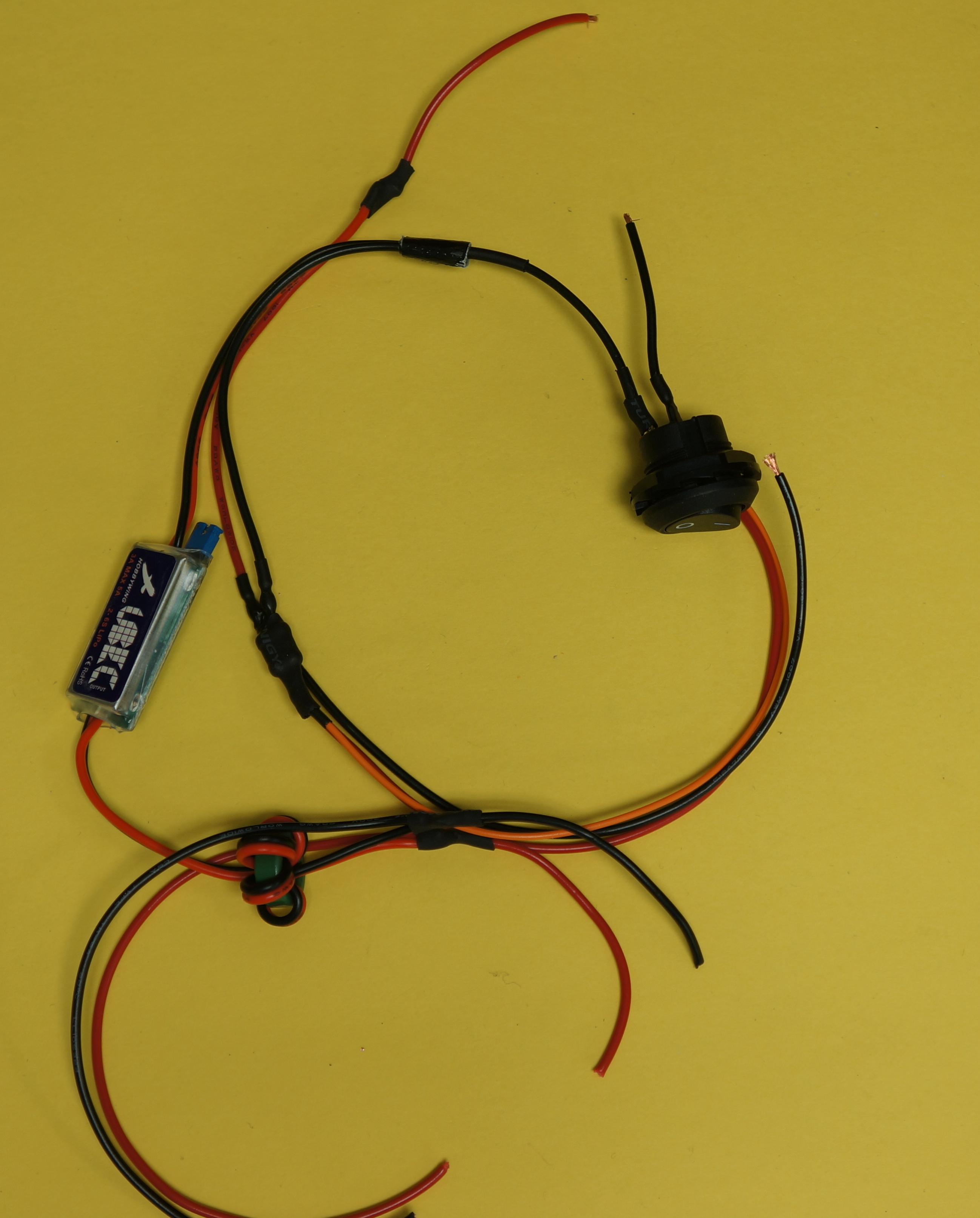
- Add shrink wrap to all the solder joints
It should end up looking like the image on the right.
| 
Larger/Higher Resolution Picture
|
Soldering complete
The Power Circuit should look similar to the image on the right at this point
| 
Larger/Higher Resolution Picture
|
Anderson Powerpole Crimping
- Parts:
- 2 Anderson Power Pole Pair (Red, Black)
- 4 Anderson Power Pole Crimps
- Solder Power Circuit
- 1 red 2 inch wire
- 1 black 2 inch wire
- Steps:
- First strip the ends on all the wires
- Take the 2 inch lead from the switch section of the solder power circuit and the 2 inch black wire and crimp them in one Anderson Powerpole crimp
- If the wires do not fit well into the crimp it may be necessary to solder the wires to the crimp to make a stronger bind
- Repeat for the red wires using the 2.5 lead of the power circuit and the 2 inch red wire
| 
Larger/Higher Resolution Picture
|
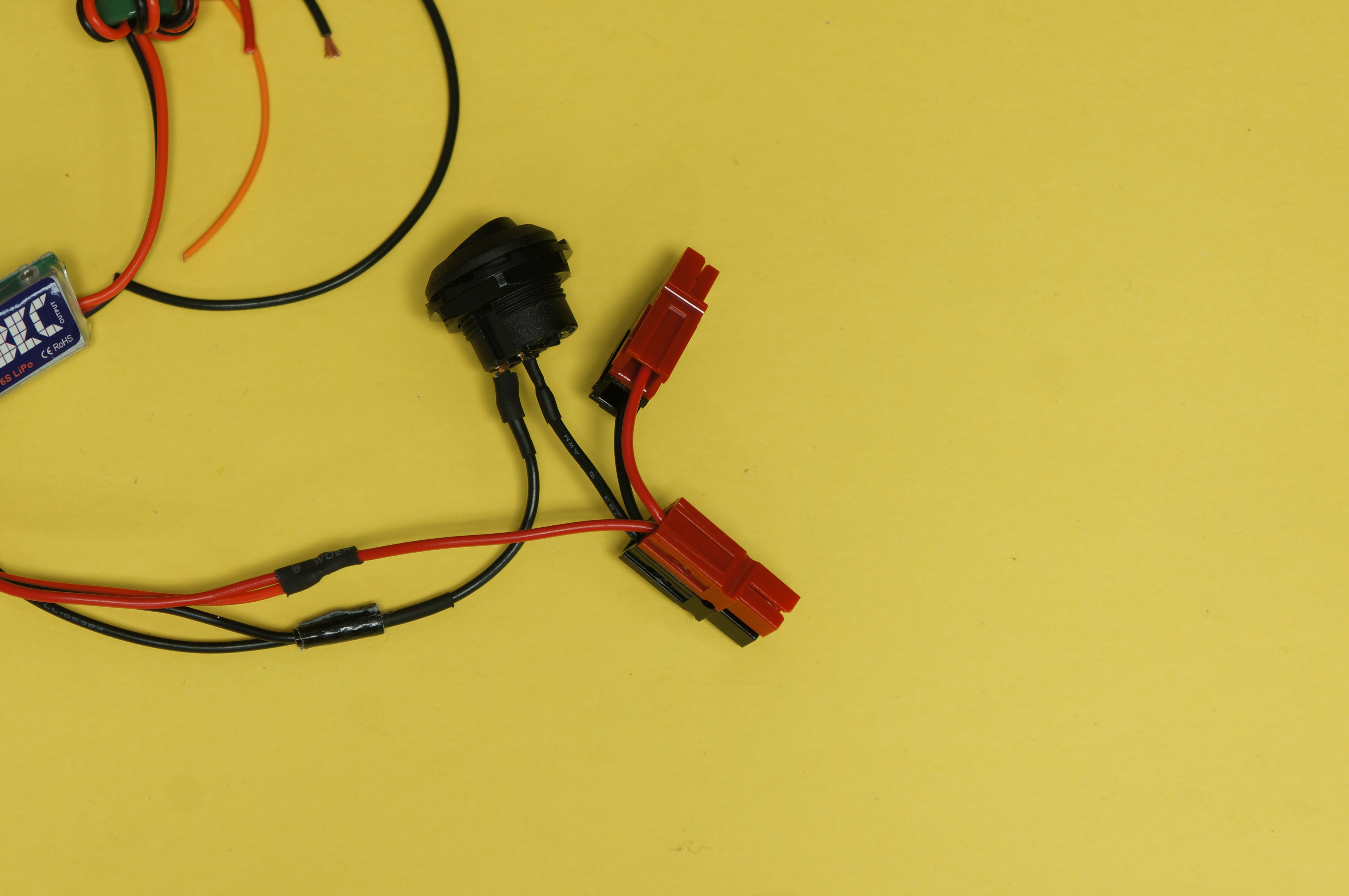
- Insert the chrimps into the Anderson Powerpole housings, attaching the housing in the direction necessary to connect to the batteries
| 
Larger/Higher Resolution Picture
|
- (Optional) Adding hot glue to secure the wires if the crimps could not hold the wires well
| 
Larger/Higher Resolution Picture
|
Crimping the Leads
- Parts:
- Solder Power Circuit
- 5 crimps
- 1 4 hole crimp housing
- 1 2 hole crimp housing
- 1 1 hole crimp housing
- Steps:
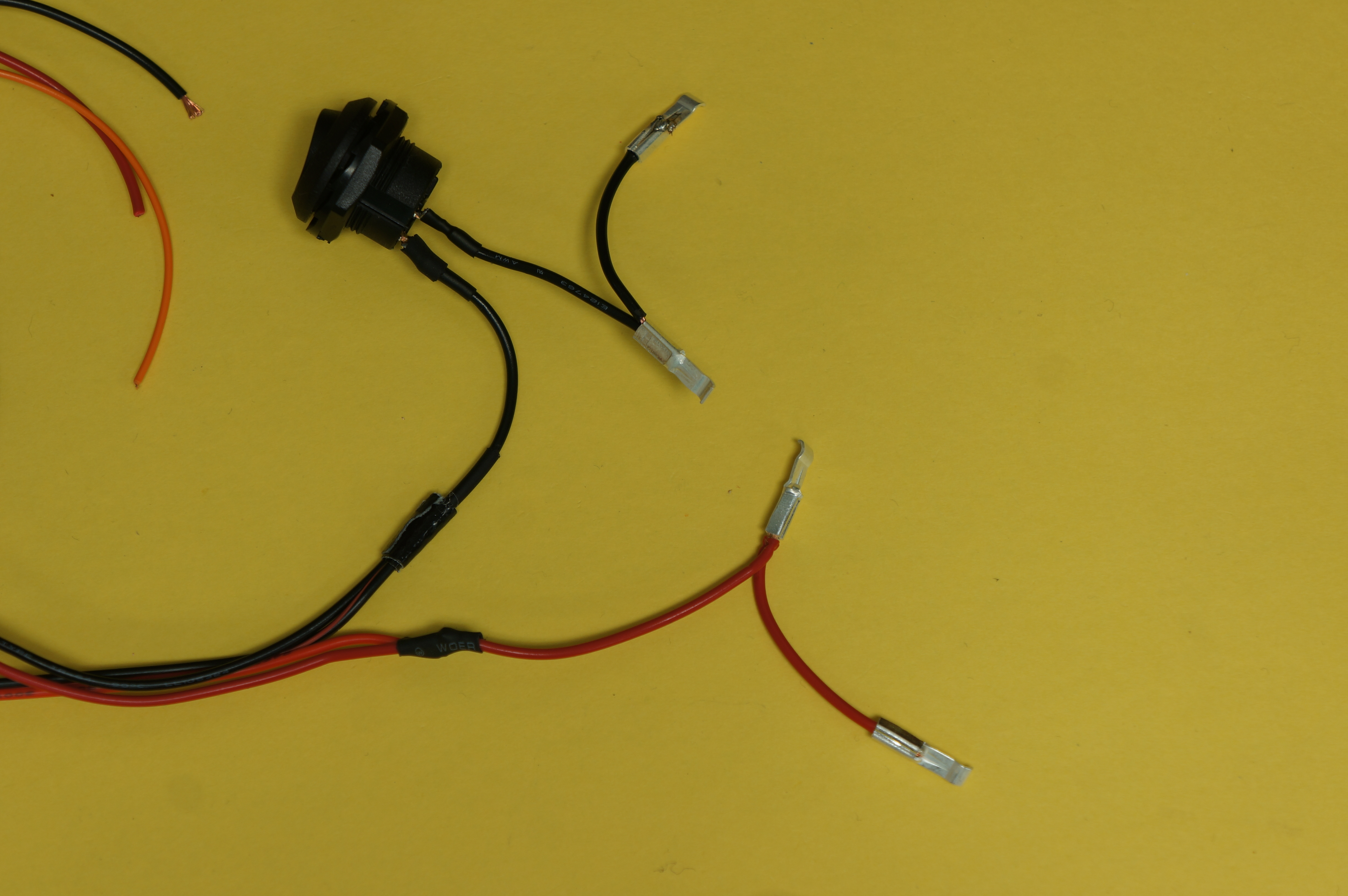
- First strip the ends on all the wires
- Crimp the leads coming off the voltage divider, red, black, other color (orange)
| 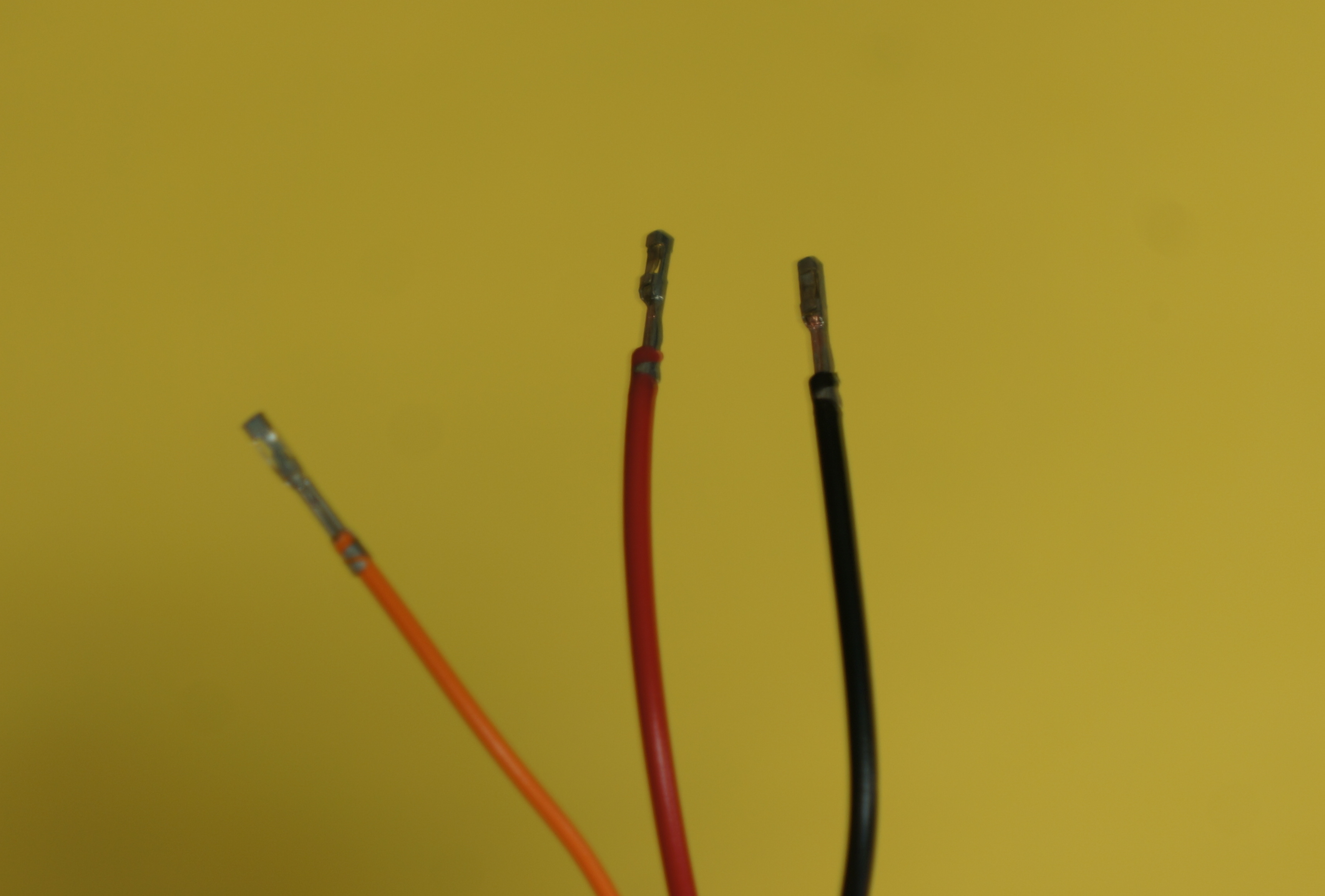
Larger/Higher Resolution Picture
|
- Crimp the 7 inch red and black wires that come after the Y split on the UBEC output side
| 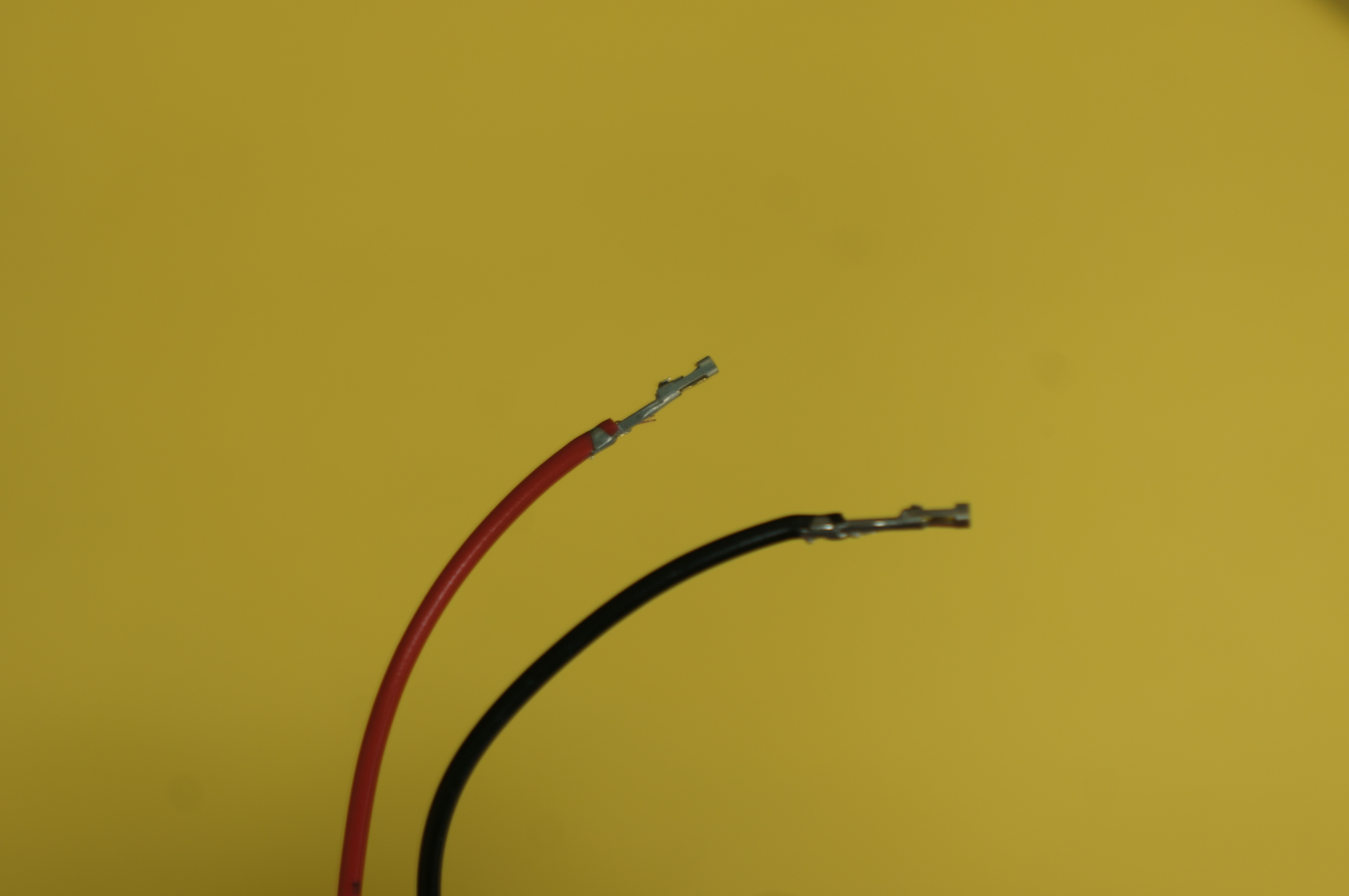
Larger/Higher Resolution Picture
|
- Insert the other color (orange) crimp into the 1 hole crimp housing
- Insert the the red and black leads after the voltage divider into the 2 hole crimp housing
- Insert the the red and black leads after the Y split in to the 4 hole housing with the two leads on the outside holes
Complete Power Circuit
The power circuit should be complete now and should look like the image on the right
| 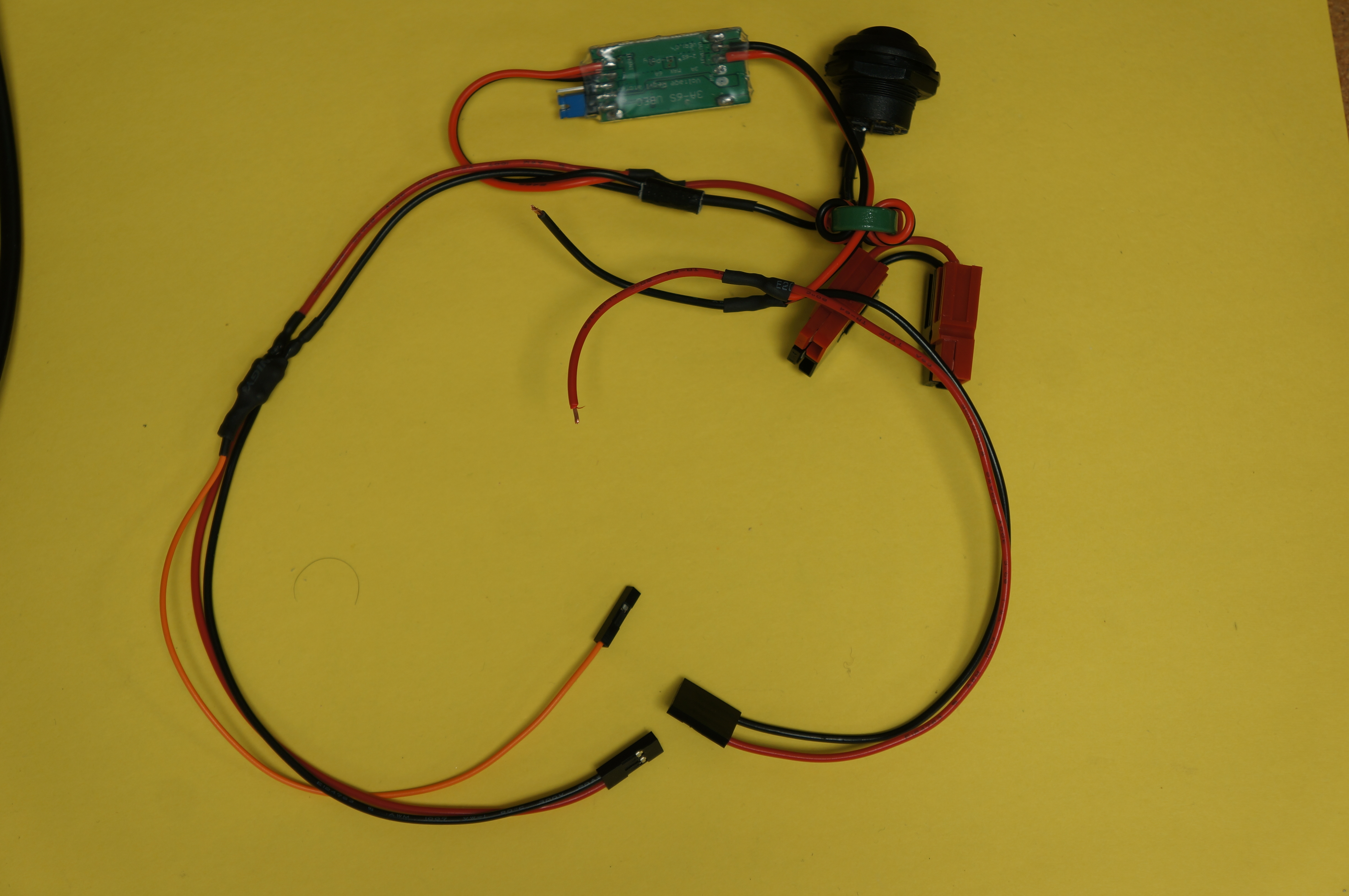
Larger/Higher Resolution Picture
|
|
|
