|
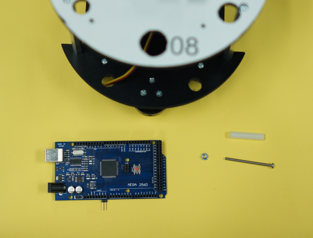
The first step of the Arduino Mega attachment is to lay out following items (shown in the image):
- Arduino Mega 2560
- One #4-40 1 3/4" (Arduino) Screw
- One #4 SPCR 1 1/4" (Arduino) White Spacer
- One #4-40 Hex Nut (Arduino)
- One #4 Washer (Arduino) (Same box as the Spacers)
At this point, you should have the parts laid out as depicted in the image to the right. (Washer not pictured)
| 
Larger/Higher Resolution Picture
|
|
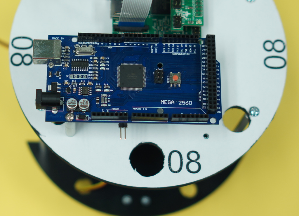
The second step is to attach the Mega to the top plate as shown.
- With the Flockbot facing away from you and the Ethernet port of the Mega facing to the left...
- Place the screw through the lower-left hole of the Arduino.
- Place the screw through the spacer.
- Put the washer between the spacer and the upper plate and run the screw through it.
- The purpose of this washer is to add 1/8" to the screw to even out the Mega.
- Attach the screw through the upper plate and secure with the nut.
- Make sure to screw it in tightly. It will hold position with just one screw.
Your space should look like the image on the right.
| 
Larger/Higher Resolution Picture
|
Arduino Mega Sensor Shield Attachment
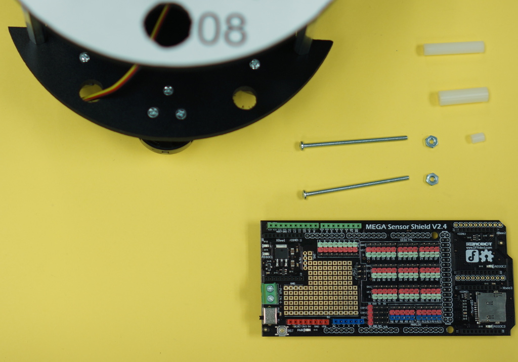
The first step of the Arduino Mega Sensor Shield attachment is to lay out following items (shown in the image):
- Sensor Shield
- One #4 SPCR 1 1/4" (Arduino) White Spacer
- One #4 SPCR 1" (Arduino) White Spacer
- One #4 1/4" Spacer (Rasp Pi) White Spacer
- Two #4-40 2 1/4" (Arduino) Screws
- Two #4-40 Hex Nut (Arduino)
- One #4 Washer (Arduino) (Same box as the Spacers)
At this point, you should have the parts laid out as depicted in the image to the right. (Washer not pictured)
| 
Larger/Higher Resolution Picture
|
|
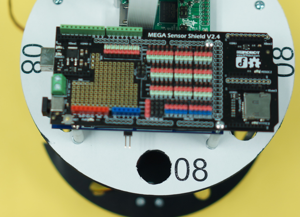
The second step is to attach the Mega to the top plate as shown. Again, with the Flockbot facing away from you.
- Align and attach the Sensor Shield to the Arduino Mega
- This will take a lot of even pressure and patience. There are a lot of pins.
- Be careful to do this evenly to avoid any bent pins.
- Attach the lower-right screw through the hole.
- Run the screw through the 1 1/4" riser.
- Put the washer between the spacer and the upper plate and run the screw through it.
- The purpose of this washer is to add 1/8" to the screw to even out the Mega.
- Run the screw through the Upper Plate and secure it with a nut.
- Place the small 1/4" spacer under the remaining hole in the Raspberry Pi
- Attach the upper-right screw through the hole.
- Feed the screw through the 1" riser, which will fit in the space between the Mega and the Raspberry Pi.
- At this point, continue feeding the screw through the Raspberry Pi and the 1/4" spacer between the Pi and the upper plate.
- Secure with the remaining nut.
Your space should look like the image on the right.
| 
Larger/Higher Resolution Picture
|
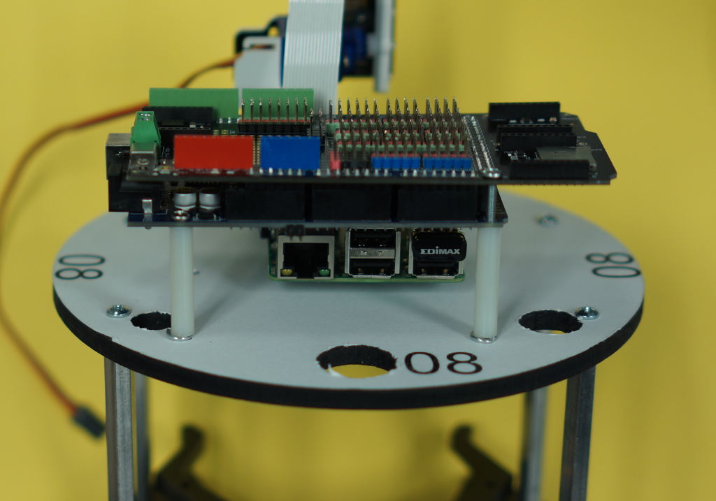
|
The same image from the side shows the two washers between the spacers and the upper plate.
| 
Larger/Higher Resolution Picture
|
Flockbot Wheel Servo and Wheel Watcher Attachment
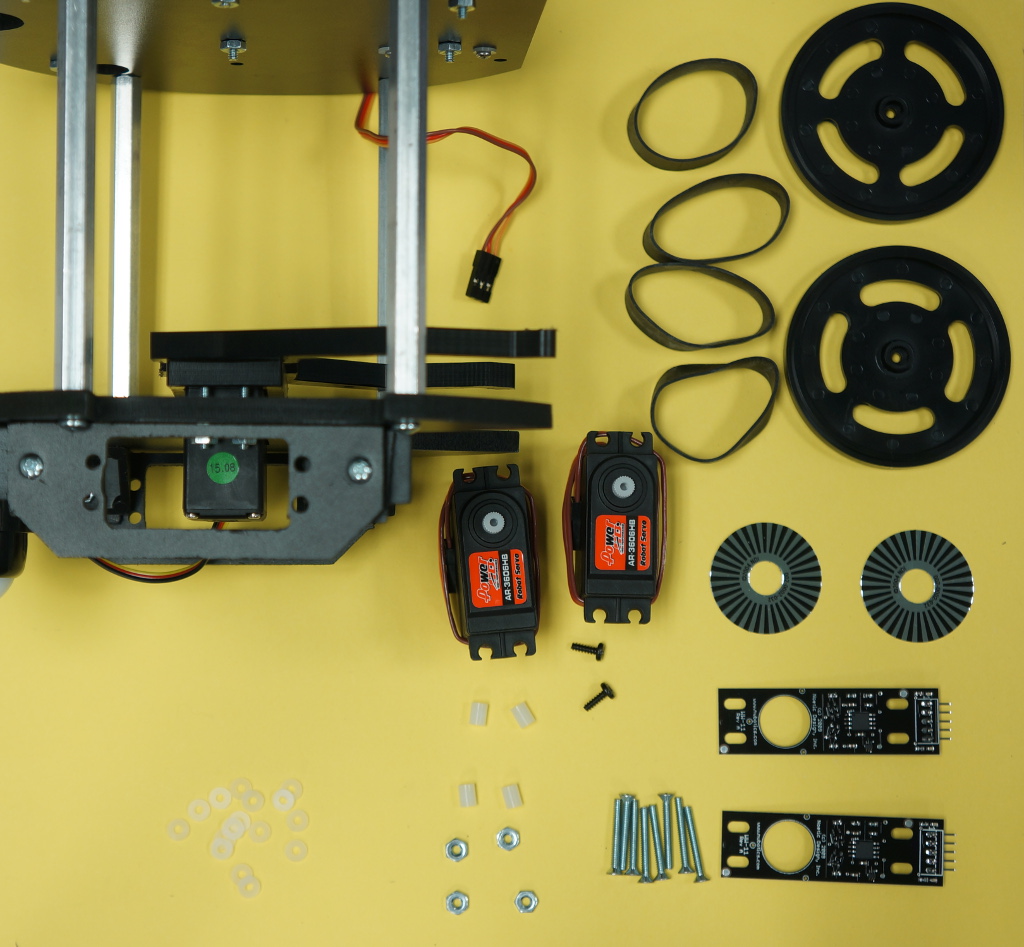
The first step of the Wheel Watcher attachment is to lay out following items (shown in the image):
- Two HD Wheel Servo
- Two WW-11 (Rev A) Boards
- Two Wheels (with 4 Rubber Bands)
- Two Black Servo Screws (In HD Wheel Servo Box)
- Two WW-11 Stickers
- Eight #4-40 Flat 7/8" Screws (Wheel)
- Four #4-40 Hex Nut
- Eight #4 1/4" Spacer (Rasp Pi)
- Sixteen #4 1/16 Spacer (Wheel)
At this point, you should have the parts laid out as depicted in the image to the right. (Washer not pictured)
| 
Larger/Higher Resolution Picture
|
|
Now, you will be performing the following steps once for each side of the flockbot:
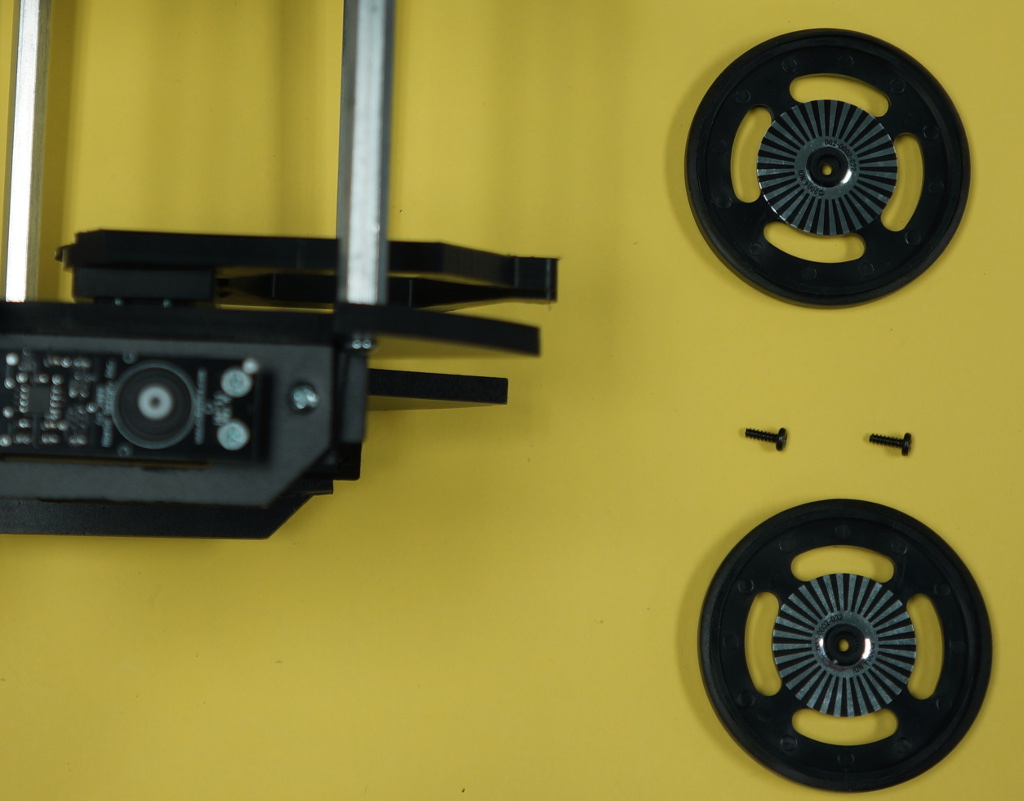
The second step is to attach the first HD Servo to the servo flange.
- Insert the Servo into the Flange as shown, with the servo wire facing the Front of the Flockbot
- Ensure the servo wire is coming out towards the front of the robot (Gripper side)
- Place the WW-11 over the servo as shown.
- Use the provided WW Alignment Tool (plastic disk) to align the WW-11 with the Servo
- Attach the WW-11 as follows (May be adjusted to perform the build easier):
- Insert the #4-40 Flat 7/8" Screw through the four holes of the WW-11
- Between the WW-11 and the Servo needs to go:
- One #4 1/4" Spacer (Rasp Pi)
- Two #4 1/6" Spacer (Wheel)
- When inserted properly, the spacers should take up all of the room between the WW-11 and the Servo.
- This will ensure a properly tightened screw.
- Now, attach the #4-40 Hex Nut to the back side of the servo to complete the mount.
Your space should look like the images on the right.
| 
Larger/Higher Resolution Picture
|
|
| 
Larger/Higher Resolution Picture
|
|
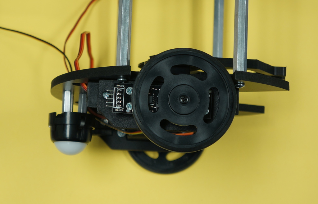
Now, perform the wheel construction:
- First, apply the stickers to the inside of the wheels.
- Second, attach the wheel on to the servos with the Black Servo screws.
| 
Larger/Higher Resolution Picture
|
|
| 
Larger/Higher Resolution Picture
|
|
Continued in Construction Three (Power Circuit)
|
