TrackingHardware
Software
Mega PlanEtc. |
Main /
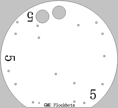
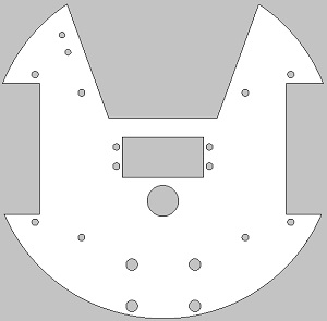
PlatformsThe robot is a two-platform design: the top platform is shaped to push objects, and the bottom platform is shaped to snag small objects in a well where they can be gripped. The platforms are largely derived from the 7 inch black Rigid PVC Round Base and Circular Base with Wheel Cutouts at Budget Robotics. CAD drawings will be provided in the near future for the two plates. One note: sand the pointy edges of both decks to round them slightly.
The Main Computer The Raspberry Pi Rev.B features
The Raspberry Pi computer runs a custom variant of the Debian Linux operating system called Raspbian. This provides native access to one of the largest code repositories for linux. Our project is coded in a mixture of C and C++, with Lua behavioral scripts. This system also has OpenCV loaded for image processing from the Raspberry Pi Camera. The Microcontroller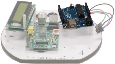 We use the Arduino Uno microcontroller.
More information on the Arduino Uno is available at their website: http://arduino.cc/en/Main/arduinoBoardUno. The Arduino Uno attaches as shown in detail in the Construction sections, uses three risers. The purpose of these risers is to enable access to the HDMI port of the Raspberry Pi computer and to assist in wiring management to contain all of the cables within the platform bounds. 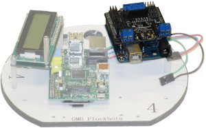 The Arduino Uno uses a custom shield to assist with connecting servos to the microcontroller. This shield, shown below, is the DFRobot IO Expansion Shield. This shield provides the inputs for the batteries and provides more convenient headers for directly connecting the servos to the microcontroller. The Power Switch The switch is a standard black, unlit rocker switch purchased at Radio Shack. The power switch is slightly too large for the hole in the default platform. You'll need to enlarge the hole by a smidgen using a X-acto knife saw, then smooth it with some sandpaper. The power switch connects to the battery via a Female Standard-Size Tamaya Connector (the battery should have a Male). You can purchase such connectors at Radio Shack or online at a variety of outlets.
The Aluminum Risers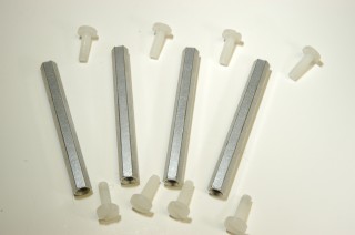 Budget Robotics sells risers in a variety of lengths, but we've found that to pack the stuff we want into our robot comfortably, only the very largest 4" Aluminum risers will do. The risers are more than tall enough to clear normal sized soda cans, making them ideal targets for collection. The IR sensors are mounted much higher than the top of those cans, so IR detection of such objects will be prevented. ServosThe robot has four servos:
Purchasing information for Servos can be found on Parts List page. The continuous-modified servos are attached to the platforms using "flange-style' servo mounts from Budget Robotics. You'll find that the L-bracket supports for these mounts poke very slightly into the gripper well of the bottom deck. You'll need to shave off the poking-in plastic either with sandpaper or with an X-acto knife. WheelsIn particular, the wheel wells are a good fit for Budget Robotics' various O-ring wheels. Originally, the wheels were sourced from a company that used Acroname as a distributor, however, this company is no longer in business and Acroname no longer has any related parts. We are presently looking for a new source for the wheels. Wheel Watchers (Wheel Encoders)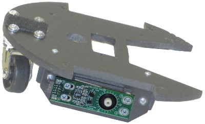 Wheel encoders use a stripped pattern of light and dark bands and a set of two infrared (IR) sensors to detect wheel motion. The sticker is placed on the wheels and sticker's bands pass the IR sensors as the wheel moves. The IR sensors (with software) can count the number of "ticks" of the wheel, and thus, the distance of the wheel. The software can use this distance to determine the velocity. Our robots use a rather expensive route, a pair of wheel watchers from Nubotics. It has two so that the encoder will be able to determine which the direction the wheel is moving. These encoders may need some additional equipment from Nubotics. Nubotics has provided a link which has good instructions on mounting the wheel watchers. There is an animated tutorial with sound that will help those who need a step by step. A less expensive approach is to build your own encoders. SeattleRobotics has a good page on this here. Here's a great PostScript program for encoder disks, which can be easily modified: GrippersWe got grippers from Robodyssey and made the following modifications to them by hand (done the same way for both gripper arms): 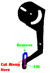 Well, that's not quite true. Robodyssey kindly filled in the purple regions on our behalf. They offered to slice them as we defined above and we should have taken up their offer. You should make this request: the modified version as defined above work much better are necessary to grab coke cans etc. Installing the Gripper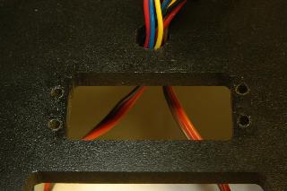 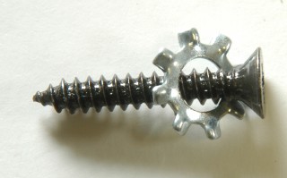
Bump Sensor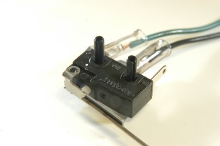 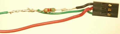 The bump sensor is a rectangular box with two extensions from one corner and the middle of the rectangular box. Creating the switch to attach to the Brainstem is simple. You will need:
The bump sensor is a simple microswitch with three connections; let's call them A, B, and C. Depressing the switch connects A and B together and disconnects C. Releasing the switch connects B and C together and disconnects A. You'll need to use a multimeter work out which are which, depending on the switch. You'll then want to hook wires up to A and B. In our switch, B is the center A is closest to the hinge. If you mess up which connection is which, the worst that can happen is your switch operates the opposite way than intended, or doesn't work at all. You'll know. (Yes, we note that in our pictures the wires don't match -- oops! It doesn't matter which wire goes to which connection). You will need to solder the first wire to current. After you have completed your soldering job, you are ready to solder the resistor to the signal. First you will cut off the plastic that covers the second peice of wire. You will wrap the access wire on the resistor. You will now solder together the helix you have created between the two wires. You know have a wire that has two ends. The Single wired end will go into the signal extension on the bump sensor. Repeat the same soldering technique as you did for the current. You now have a total of three wires pointing out of your bump sensor. Note: Now is a good time to measure the distance between where you will mount the sensor and where it will get plugged into the Arduino. Any excess wire can be cut down before crimping to avoid a mess atop the robot. Crimp each of the three wire ends and add a touch of solder to hold the confirm the wire is held in place. You can now push the crimps into the housing. Always check to see what side is signal and what is going into ground. They wires should go in CURRENT/SIGNAL/RESISTOR. Plug in and test your bump sensor! The bump sensors are mounted with two 3/32" x 1/2" metal tension pins. You will need to drill two 3/32" holes in both the upper and lower decks. See the Construction sections for more details. The Batteries and Battery ChargerThe batteries are 7.2-volt 6-cell "C" NiMH packs with Standard size Anderson Power Pole connectors. There are some important things you need to know about them.
Sharp IR Distance Sensors and their Frame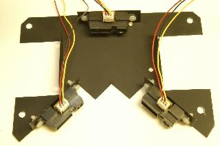 To save weight, hanging under the top platform is a thin aluminum frame to support up to five Sharp IR distance sensors. The frame is made of lightweight aluminum flashing, spray-painted black. You can buy flashing at Home Depot in small sheets. Here is a template for cutting and bending the frame and punching holes in it (which can be done with simple tools): PDF document or Freehand 10 Document. The frame supports:
In the Construction 2 photographs we show our hand-cut version of the frame, which is close to but not precisely the same as the above template. The robot constructed in the photograph also has only three infrared sensors; the two side sensors were omitted. The Caster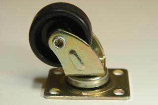 We used a 1" plate (non-stem) caster. These small casters can be purchased for about $1 at Lowes, but not Home Depot, where 1-1/2" is the smallest. Unfortunately there's no standard for the spacing of the caster holes. After we purchased our deck plates from Budget Robotics, Lowes changed their caster supplier on us and the holes didn't quite fit. We fixed matters by drilling down the center of all four deck holes with a 1/4" drill bit. The caster is mounted to the deck with large (3/4" #8?) machine screws, some bolts, washers, and lock washers. The washers are used to raise the caster until the robot is level. See the pictures in the Construction 1 section. |
||||||||