A more detailed set of pages will be forthcoming during the coming Summer break period.
|
| Construction 2 >>>
|
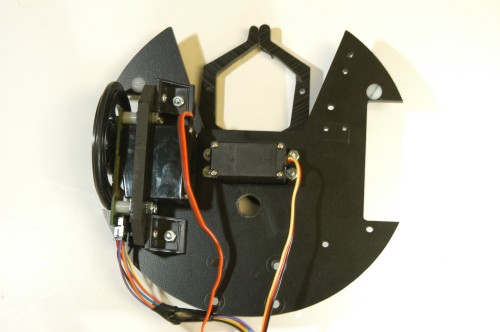
Cut/Drill Bottom Deck
See the Platforms page for detailed diagrams and deck specifications.
The gripper well is cut into a flat U shape. The wheel wells are all cut in such a way that the wheels will not extend beyond the base. The rectangular hole in the middle is for the gripper servo. The four holes on the back side of the deck are for the caster. The circular hole in the center is for running all the cables to the top deck (we'd make that a bit larger in the future). At this stage you should also drill the small holes to hold the gripper servo: be careful, as these holes must be done very precisely and close to the servo hole. Also, you should drill the two small holes to hold the bump sensor.
| 
Larger/Higher Resolution Picture
|
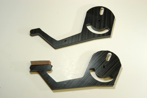
Gripper Modification
On the bottom is the standard gripper from Robodyssey. They kindly "filled in" the end of the gripper arm for us (see the diagram in the Hardware section).
We eventually further modified the arm as shown at top, by slicing off the back tab. This cut allows the gripper to more easily snag soda pop cans.
| 
Larger/Higher Resolution Picture
|
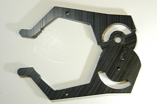
Grippers Together
This is how the grippers will be placed on the bot.
| 
Larger/Higher Resolution Picture
|
Gripper Servo Placement and Attach Grippers
Attach the gripper servo into the slot and screw it in. For the grippers we used, make sure the servo gear is on the left when looking at the platform face up. Screw the four nylon bolts for the risers through the bottom deck.
The gripper is screwed onto the servo as shown. Note that the provided screw to attach it to the servo is too short. See the Platform section for discussion about where to get a longer screw (it's unusual) and other hints for mounting the gripper.
You'll want to mount the gripper so that the arms are set to a default location of your choosing for the "0" (middle) setting of the servo. The easiest way to do this is to attach the servo to a Brainstem, then power up the Brainstem. The servo will center itself; you can then attach the arms as you see fit. We suggest attaching them so that they are just recessed into the robot cavity as shown. Don't let them touch the aluminum risers, or the servo will use up power constantly trying to push against the risers to get itself in its "0" position.
| 
Larger/Higher Resolution Picture
|
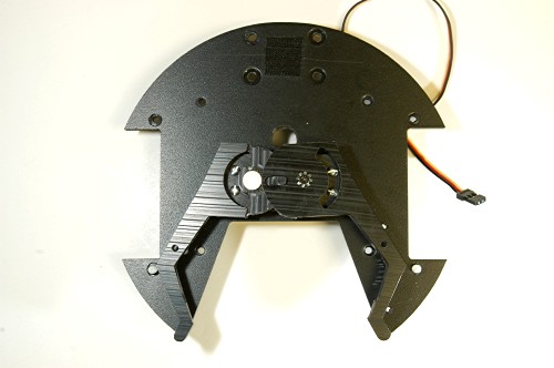
Attach Servo bracket/Wheel Watcher to Servo
Before doing anything to the servo mounting bracket, you must first mount the small angle bracket. If you do not attach these now you will have to remove other things that you have added later. The Wheel Watcher will get in the way.
The next step is to attach the servo mounting bracket to the servo. This is easily done by placing the bracket over the servo and attaching it with screws and nuts.
The Wheel watcher should be attached on top of the other items. The ends of the wires will be attached to two 4x1 crimp housings which will hold four crimped wires (two of the Wheel Watcher's wires will be unused).
| 
Larger/Higher Resolution Picture
|
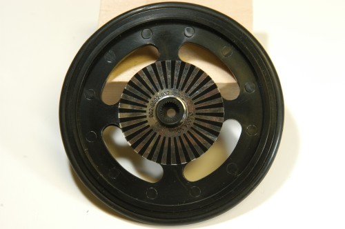
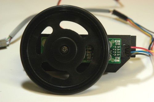
Attach Silver/Black Sticker and Wheel
The next step is to attach the Silver/Black sticker to the inside well of the wheel. After that attach the wheel to the servo assembly.
| 
Larger/Higher Resolution Picture
|
Completed Servo Assembly
This is a picture of the completed servo assembly. Repeat the above steps to complete the second servo assembly. Note that one servo (and Wheel Watcher) must be mounted "backwards" from the other one so that they both face forward on the robot.
| 
Larger/Higher Resolution Picture
|
Attach Assembly to Base
Attach the completed assembly to the bottom of the base deck. The angle brackets protrude slightly into the gripper well, and were must be shaved off to eliminate any snagging. Attach the other assembly to the base same as above. Now is a good time to complete the wheel watcher wiring with crimps and housings.
| 
Larger/Higher Resolution Picture
|
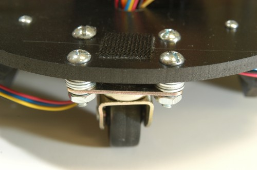
Attach Caster to Base
Attach the caster to the base using washers between the caster and the base to keep the caster level. If the caster is not close to level it will not function properly. Place a small piece of velcro between the caster screws to hold the battery in place.
| 
Larger/Higher Resolution Picture
|
Attach Risers and Feed Cables
Attach the risers to the deck. Also feed all cables from the bottom up through wire hole.
| 
Larger/Higher Resolution Picture
|
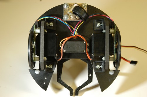
Completed Underside
Here there should be wires from the two encoders and three servos through the lower hole.
| 
Larger/Higher Resolution Picture
|
|
| Construction 2 >>>
|

