
TrackingHardware
Software
Mega PlanEtc. |
Main /
GumstixmodsWe had to the modify the Waysmall buddy board to get I2C working. You'll need to make an I2C cable for the Gumstix, soldering one end to the waysmall board, and attaching the other end to a 6-pin female connector. We will be using Acroname's standard for I2C connectors: 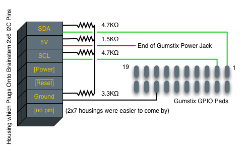 Our Gumstix I2C cable will use SDA, 5V, SCL and Ground. One end of our Gumstix I2C cable attaches to the Brainstem I2C pins via crimps and a 7x2 housing. Double check the ordering of the Brainstem pins, especially the power! Also, a resistor bundle is needed to change the voltage from 5V to 3.3V. We attached the resistor bundle to the top row of the Brainstem's I2C pins. 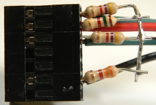 The resistors correspond to the following diagram which pulls the voltage down from 5V to 3.3V: 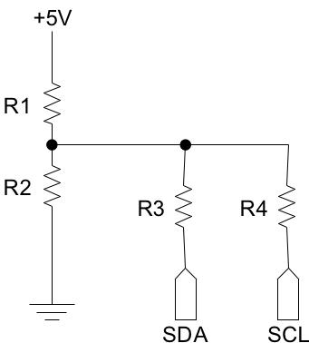 R1 and R2 are a matched pair, such that Vout = Vin * R2/(R1 + R2). You'll need two resistors which output 3.3 volts when Vin is 5 volts. We used spare resistors in the range of 100Ω to 3KΩ. R3 and R4 are pullup resistors, whose values are not so critical. Anything in in the 2KΩ to 8KΩ range should work fine -- we used 4.7KΩ resistors. The other end of the Gumstix cable attaches to the Waysmall board. Three of these connections will come from the back of the board: 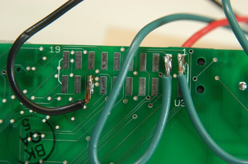 From left to right, the connections are Ground, SLC, and SDA. Use stranded wire, not solid, and only use black for ground. Make sure that the wire that is attached to the GPIO pads on the Waysmall board aren't able to reach any adjacent pads. Also, remove the Gumstix from the Waysmall board before you start doing any soldering. The Waysmall board is cheaper than the Gumstix computer. Power for the Gumstix can be provided by soldering a wire to the power jack on the top of the waysmall board: 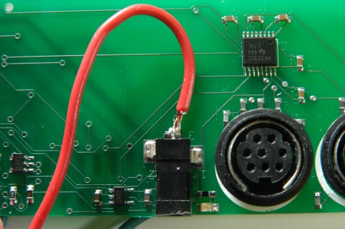 Be sure to solder a red, stranded wire to the end of the power jack. The sides are ground, not positive voltage, and if you solder to them instead of the end you'll create a short circuit. This red wire should connect to the 5V pin on the connector not the power pin. The final modification is to the Gumstix plastic case. There is no room for the I2C wires, so you'll need to cut part of the case: 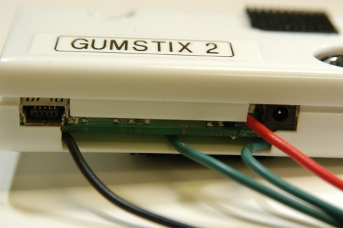 Modifications for Older Gumstix Serial BoardsOn the older Gumstix, the engineers relied on a hack to implement Bluetooth which resulted in stealing To modify the original boards to use a second serial port, you must cut two traces and solder two wires to enable 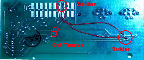 |