| <<< Construction 2
| Construction 4 >>>
|
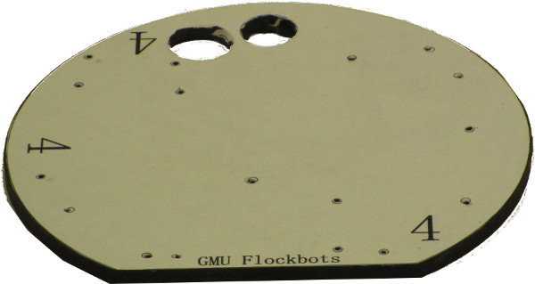
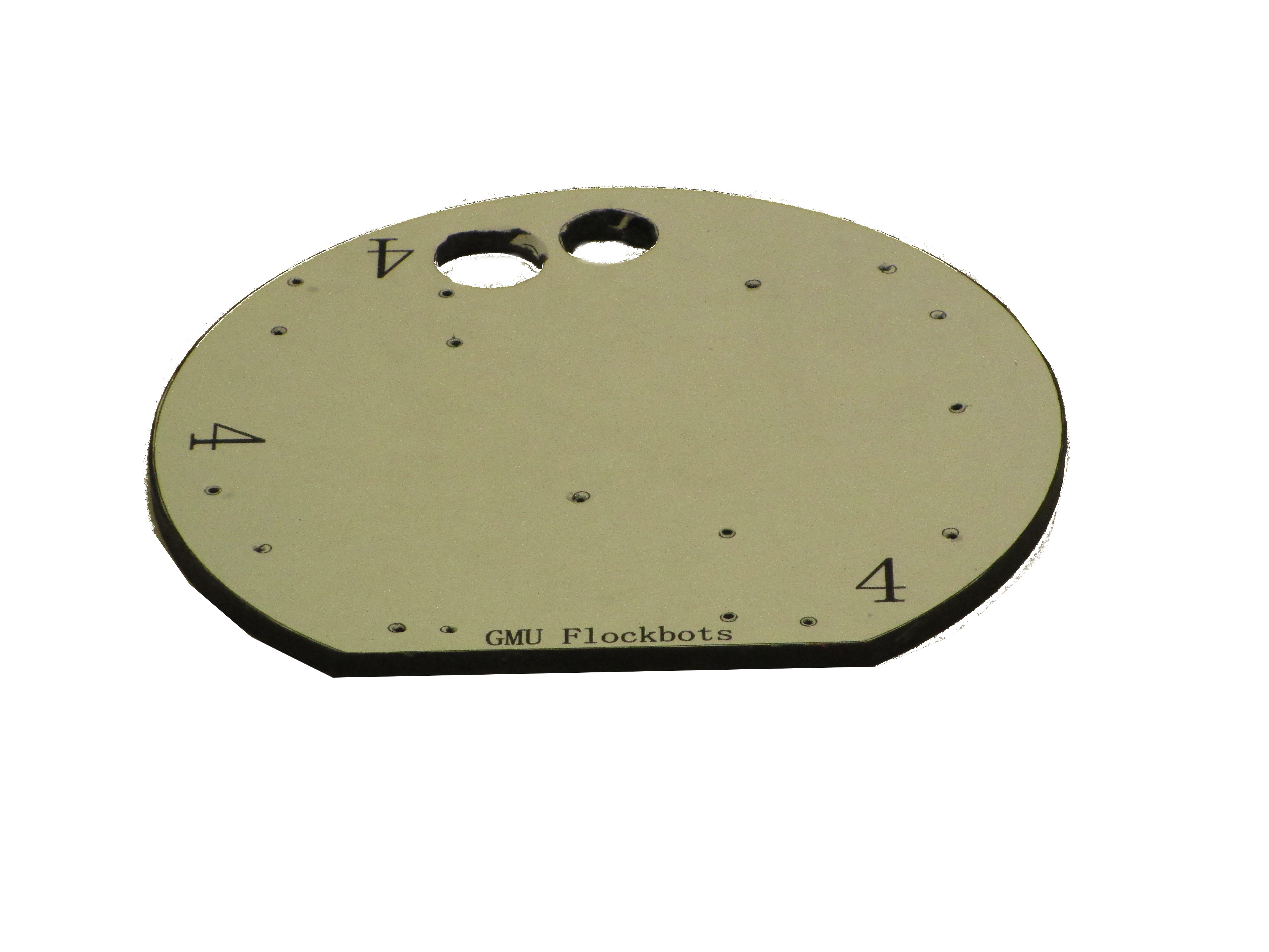
Top Deck
See the Platforms page for detailed diagrams and deck specifications.
The top deck has a flat front to act as a pusher. The large hole on the right is for the power switch, and the smaller hole is for all the wires from below.
| 
Larger/Higher Resolution Picture
|
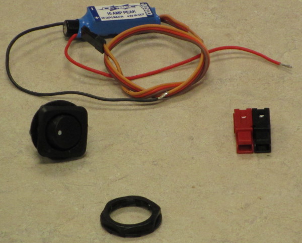
Power Switch and BEC
The power switch is between the battery and the Arduino Uno. The ground wire from the battery is wired through the switch. From there, the wiring follows the following guide for the Castle Creations Battery Elimination Circuit (BEC).
The positive and negative wires need to be split after the power switch. One set of each wires in directly to the PWR_IN inputs on the Arduino Uno DFRobot shield. The other pair of wires connect to the BEC and then the BEC will connect into the Servo_PWR input of the shield.
This ensures that the Arduino gets the direct voltage, while the servos will always get a directly metered 5VIN.
| 
Larger/Higher Resolution Picture
|
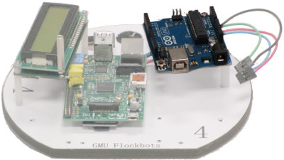
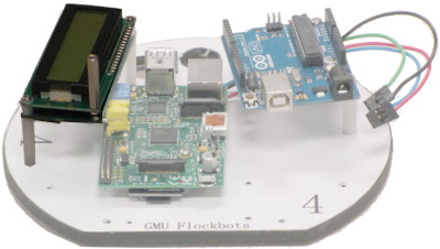
Raspberry Pi Rev.B
Our main system board is the Raspberry Pi, Revision B. This is the main computer board that processes all incoming communications and directs the Arduino microcontroller. This attaches to the top board using two screws, nylon washers, and 1/4" risers.
| 
Larger/Higher Resolution Picture
|
Arduino Uno
Our microcontroller for servo and sensor control is the Arduino Uno. This board attaches to the top plate as shown, using a set of three risers. Of particular note, because we will also be adding on the DFRobot shield, only two of these risers are attached directly to the Arduino. The third riser, longer than the other two, is attached through the Uno and connects to the DFRobot shield, which will be shown in the following section.
There is no wiring associated directly with the Arduino Uno.
| 
Larger/Higher Resolution Picture
|
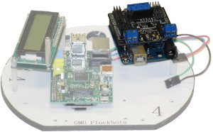
DFRobot Shield
The DFRobot DFRduino I/O Expansion Shield attaches to the headers on the Arduino Uno to provide a breakout more compatible with servos. The shield is divided into two sides: analog and digital. The servos, sensors, and components are wired into this shield in accordance with the Wiring Guide instructions.
The two power inputs mentioned above in the section concerning the Castle Creations BEC and Power Switch connect to the two listed ports on this shield.
| 
Larger/Higher Resolution Picture
|
LCD
The LCD screen used is the Matrix Orbital LVPK162-12. This uses a standard 4-pin I2C connector, consisting of power, ground, clock (SCL), and data (SDA). The wiring of the LCD connects to the DFRobot shield as listed in the Wiring Guide. The pins used on the Shield are not I2C native connections, however, we are using a software I2C library to emulate this functionality.
| 
Larger/Higher Resolution Picture
|
Raspberry Pi Camera and Pi-Pan Servo Kit
The camera is the Raspberry Pi Camera, which connects directly to the Raspberry Pi board. The tilt-servo kit is available from OpenElectrons. The instructions for assembly and mounting are at http://www.openelectrons.com/index.php?module=pagemaster&PAGE_user_op=view_page&PAGE_id=20.
| 
Larger/Higher Resolution Picture
|
Top Bump Sensor
The top bump sensor attaches in the same manner as the lower bump sensor. The entire top plate then attaches to the lower base for the completed robot, as shown in the following image.
| 
Larger/Higher Resolution Picture
|
|
|
